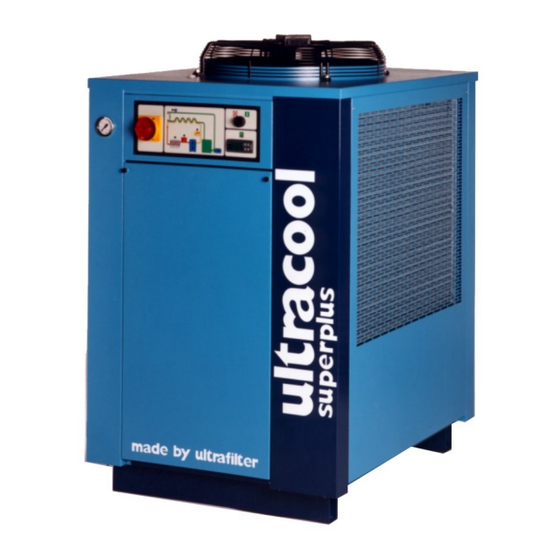
Summary of Contents for Lauda Ultracool Superplus series
- Page 1 OPERATION MANUAL ultracool mini 0140 Indigo 50/60 Hz Rev: 1 Date: 30.04.03 Ref: MI-080...
- Page 2 Warnings Warnings This Operation Manual is to be followed by all persons working with the unit. It is imperative that this Manual is made freely available at all times to service personnel and is kept at the point where the unit is installed. The basic maintenance, as indicated in point 5.1, should be carried out by properly trained personnel and, if necessary, under the supervision of a person qualified for this job.
-
Page 3: Table Of Contents
Table of Contents Table of Contents 1 Introduction General notes Safety regulations 2 Installation Reception and inspection Transportation Site Installation Identification labels on the ultracool unit Water connection Electric connection 3 Start-up Operating conditions Before the start-up of the ultracool unit Chiller strat-up 4 Control Panel Components of the control panel... -
Page 4: Introduction
Introduction 1 Introduction 1.1 General notes • This water chiller complies fully with EC-machine directives and is UL and CSA listed. • The Company does not accept responsibility if safety regulations are not met during handling, operation, maintenance and repair, even though these may not be strictly stated in this operation manual. -
Page 5: Installation
Installation 2 Installation 2.1 Reception and Inspection On receipt of the ultracool unit, it must be inspected for damage during transport. In the case of any damage, external or internal, this cannot be referred to the manufacturer because all units are checked before dispatch. - Page 6 Installation 2.4 Installation The ultracool units must always operate with the panels closed to enable the inlet of fresh air only through the condensor. If the operation of the ultracool unit is with ambient temperatures below 5ºC (41ºF), ethylene glycol must be added to the water of the installation.
-
Page 7: Water Connection
Installation 2.6 Water Connection It is necessary to install a water filter at the inlet of the chiller in order to avoid free particles in the water, which could block the evaporator plates or damage the pump. ultrafilter will not accept any warranty for the evaporator freezing if there is no water filter. -
Page 8: Start-Up
Start-up 3 Start-up 3.1 Operation Conditions The control thermostat in the chiller will control it in order to maintain the preset cold water temperature. Water temperature at the inlet: Nominal: 15ºC (60ºF) Maximum: 30ºC (86ºF) Cold water temperature at the outlet: Nominal: 10ºC (50ºF) Minimum:... - Page 9 Start-Up 3.3 Chiller start-up When the ultracool unit is started for the first time, it is necessary to turn ON the Main power switch (element 1 in the control panel, see point 4) and wait six hours before continuing with the start-up sequence. This time is necessary for the crankcase of the compressor to heat it up.
-
Page 10: Control Panel
Control Panel 4 Control Panel 4.1 Components of the Control Panel The control panel consists of the following elements: 1. Main power switch: connects and disconnects the ultracool unit from the power supply. 2. On-Off switch: starts up the different elements that make up the ultracool unit. -
Page 11: Operating Conditions
Control Panel 10. High refrigerant pressure alarm indicator: this is lit when the pressure of the refrigerating circuit is higher than the maximum allowed. It causes the refrigerant compressor to stop. 4.2 Control Thermostat Display in ºC Display in ºF 4.2.1 Operation During normal operating conditions, the display of the control thermostat shows the cold water temperature measured by the... -
Page 12: Maintenance
Maintenance 5 Maintenance 5.1 Basic Maintenance Weekly: Verify that the water temperature indicated on the control thermostat is approximately at the setpoint. Verify the pressure of the pump. Verify the water level in the tank. Verify the state of the water filter, if the pressure drop exceeds 0.5 bar (8 psi) change the filter element. -
Page 13: Troubleshooting
Troubleshooting 6 Troubleshooting In the following chart the possible causes for an alarm are given together with their solution DEFAULT CAUSE SOLUTION RESTART PROCEDURE Lateral panels of Close the panels Disconnect the chiller Alarm due to high the housing open (On/Off and Main power pressure of the switch both Off, see point... - Page 14 Troubleshooting DEFAULT CAUSE SOLUTION RESTART PROCEDURE Water circuit Clean the water circuit, The control will go back to Low flow/temperature blocked check for closed valves normal operation when the control operates in the circuit. problem is solved continuously (see point Possible freezing Check the proportion of ethylene glycol.
-
Page 15: Technical Features
Technical Features 7 Technical Features 140 Indigo 50Hz 140 Indigo 60Hz Cooling capacity kW (ton) 15.3 (4.3) 17.4 (4.9) Water flow l/h (US gal/min) 2628 (11.6) 2566 (11.3) Water pressure bar (psi) 5.1 (74) 4.8 (70) Refrigerant charge kg (lb) R134a 14 (31) 14 (31) Compressor... -
Page 16: Log Book
Log Book 8 Log Book 8.1 Log Book Date Remarks Signature... -
Page 17: Annexes
Annexes 9 Annexes 9.1 Water quality In order to protect the water circuit of the ultracool units, the water to be cooled must have specific physical/chemical properties so that it is not aggressive. If this water is outside any of the limits listed in the table below, it can seriously damage some of the materials of the ultracool unit. -
Page 18: Spare Parts
Spare parts 10 Spare parts UC-140 Indigo 50Hz UC-140 Indigo 60Hz Amount Article number Article number Compressor 0100165000 0104710000 Condenser E3751054 E3751054 Evaporator E5293018 E5293018 Motor fan E5204252 E5204258S Pump E4521374 E4521442 Water tank E3540026 E3540026 Liquid vessel C210129000 C210129000 Expansion valve 0101807000 0101807000...


Need help?
Do you have a question about the Ultracool Superplus series and is the answer not in the manual?
Questions and answers