Lauda MC 250 Operating Instructions Manual
Circulation chiller
Hide thumbs
Also See for MC 250:
- Operation instructions manual (64 pages) ,
- Operation manual (60 pages)

Related Manuals for Lauda MC 250


Summary of Contents for Lauda MC 250
-
Page 1: Operating Instructions
The right temperature worldwide Operating instructions Microcool MC 250, MC 600, MC 1200, MC 1200 W Circulation chiller... - Page 2 LAUDA DR. R. WOBSER GMBH & CO. KG Postfach 1251 97922 Lauda-Königshofen Germany Phone: +49 (0)9343 / 503-0 Fax: +49 (0)9343 / 503-222 E-Mail: info@lauda.de Internet: www.lauda.de Translation of the original operating instructions YAWE0033 V02REV60 10/02 2 /2014 © LAUDA 2013...
-
Page 3: Table Of Contents
Table of contents Table of contents Safety..............................6 General safety instructions......................6 Intended use..........................7 Foreseeable misuse........................7 Modifications to the device......................7 Heat transfer liquid........................7 Materials............................8 Hoses............................8 Application area........................... 8 Personnel qualification........................ 8 1.10 Personal protective equipment....................9 1.11 Structure of safety instructions.................... - Page 4 RS232 interface......................... 30 4.5.1 Cable and interface test RS232................. 30 Alarm output 12N........................30 Commissioning..........................32 LAUDA heat transfer liquids...................... 32 Filling device with heat transfer liquid..................33 Establishing power supply......................34 Switching on the device......................35 Refilling heat transfer liquid....................... 35 Setting pump pressure......................
- Page 5 10.3 Disposing of packaging......................59 Technical data............................ 60 11.1 General data..........................60 11.2 Refrigeration unit........................61 11.3 Hydraulic circuit......................... 62 11.4 Voltage-dependent data......................62 General............................... 63 12.1 Copyright........................... 63 12.2 Technical changes........................63 12.3 LAUDA contact.......................... 63 12.4 EC conformity..........................63 Index..............................65 Microcool...
-
Page 6: Safety
Also store this copy of the operating manual carefully. If you lose this operating manual, contact the LAUDA Constant Temperature Equipment service. The contact details can be found in Ä... -
Page 7: Intended Use
Setting an incorrect pump pressure 1.4 Modifications to the device Any technical modifications to the machine are prohibited. Service works may be carried out only by the LAUDA Constant Tem- perature Devices service or one of the service partners authorized by LAUDA. -
Page 8: Materials
Stainless steel and temperature-resistant plastics are used. 1.7 Hoses Only LAUDA hoses are permitted to be used for the external hydraulics circuit. LAUDA hoses are hoses that are approved by LAUDA DR. R. WOBSER GMBH & CO. KG. When selecting suit-... -
Page 9: Personal Protective Equipment
Safety 1.10 Personal protective equipment Protective clothing Protective clothing is required for certain activities. This protective clothing must comply with the legal requirements for personal pro- tective equipment. Protective clothing should have long sleeves. Safety footwear is additionally required. Protective gloves CE protective gloves are required for certain activities. - Page 10 Safety Caution A safety instruction of the type "Caution" indicates a poten- tially hazardous situation. This can result in minor, reversible injuries if the safety instruction is disregarded. CAUTION! Type and source Consequences in the case of non-compliance Measure 1 ...
-
Page 11: Unpacking
Also inform LAUDA Constant Temperature Equipment Service immediately. Contact details can be found in Ä Chapter 12.3 ‘LAUDA contact’ on page 63. Accessories included as standard Catalogue Device type... -
Page 12: Design And Function
This specification in the device type is optional. It identifies water-cooled equip- ment. Available device types Device type Description MC 250 Air-cooled tabletop device with a cooling capacity of 250 watts MC 600 Air-cooled floor-standing device with a cooling capacity of 600 watts. The pump pressure can be adjusted using a bypass adjustment wheel. - Page 13 Design and function Rear side MC 250 Fig. 2: Overview of the rear side Pump connection, outlet Overflow connection Pump connection, return Rating plate Drain plug RS232 interface Alarm output Mains cable Ventilation openings Microcool...
-
Page 14: Design Of The Circulation Chiller
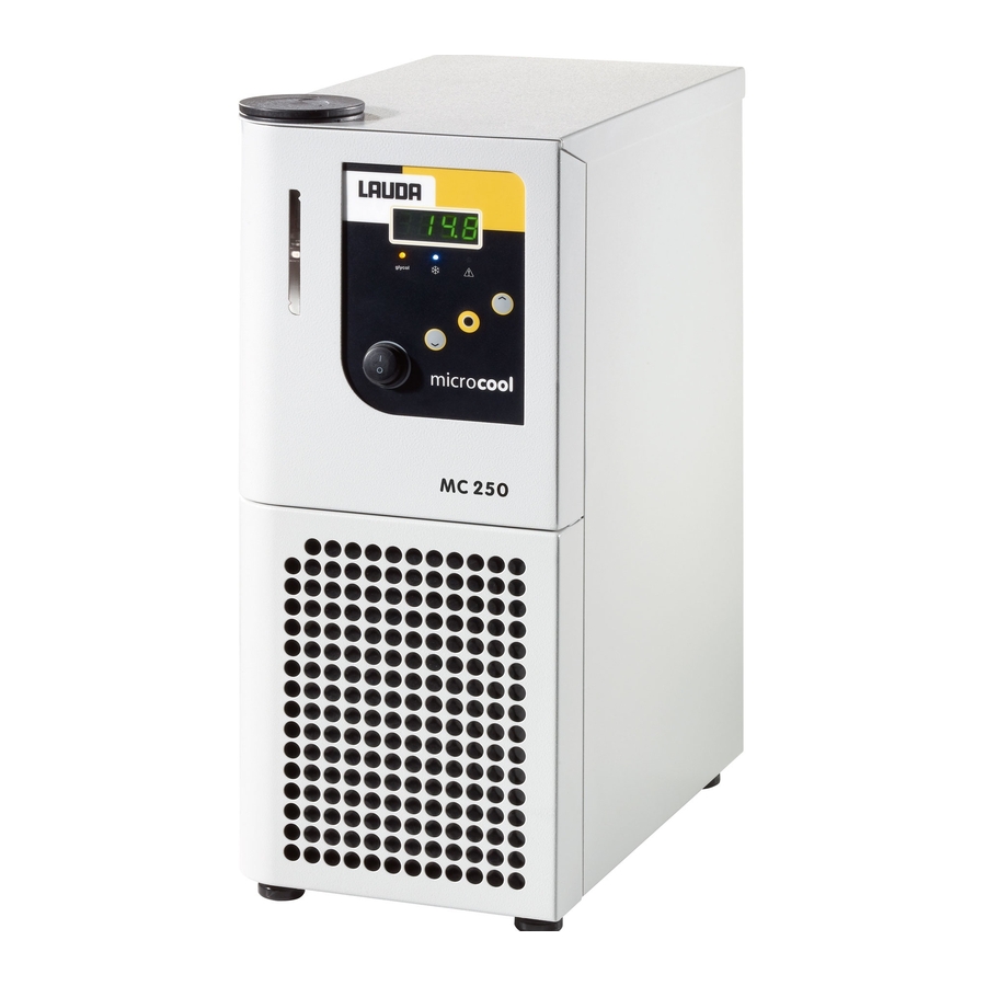
Design and function 3.2 Design of the circulation chiller Front side MC 250 Fig. 1: Overview of the front side Filler nozzle with cover Level indicator Control panel Front panel with ventilation openings Four support feet Microcool... - Page 15 Design and function Front side MC 600, MC 1200 (W) Fig. 3: Overview of the front side Filler nozzle with cover Control panel Level indicator Manometer Front panel with ventilation openings Four castors with locking brakes Microcool...
- Page 16 Design and function Rear side MC 600, MC 1200 (W) Fig. 4: Overview of the rear side Pump connection, outlet Bypass adjustment wheel Pump connection, return Overflow connection Rating plate Drain plug RS232 interface Alarm output Mains cable 10 Ventilation openings Microcool...
-
Page 17: Controls
Design and function Control panel Fig. 5: Control panel Display LEDs Display buttons Mains power switch 3.3 Controls 3.3.1 Mains power switch The mains power switch can be put in the following positions: In position [I], the device is switched on. ... -
Page 18: Display Buttons
Design and function 3.3.2 Display buttons Fig. 6: Display buttons UP arrow button ENTER button DOWN arrow button Functions in the display of the device can be controlled using the display buttons. A selection in the display can be confirmed with the ENTER button. -
Page 19: Function Elements
Design and function 3.4 Function elements 3.4.1 LEDs for function display Fig. 7: LEDs Yellow LED Blue refrigeration LED Red error LED Each device has three LEDs with the following functions: The yellow glycol LED lights if Kryo 30 is necessary as heat transfer liquid. -
Page 20: Manometer
Design and function Pump The devices are equipped with a magnetically coupled pressure pump. Further information about the technical data of the pump and the pump characteristic curve can be found Ä Table on page 62. 3.4.3 Manometer The device types with bypass have a manometer for reading the set pump pressure. -
Page 21: Interfaces
Design and function Compressor A hermetically sealed compressor is used in the refrigeration unit. The compressor is equipped with overload protection which trips on the compressor temperature and compressor current consumption. Condenser Depending on the device type, an air-cooled or water-cooled condenser is used in the refrigeration unit. -
Page 22: Rating Plate
Class according to German standard for electrical laboratory DIN 12876-1 equipment 3.6 Serial number The serial number of a LAUDA device has the following structure: LAUDA catalogue number Year of manufacture The year is indicated with two digits. -
Page 23: Before Commissioning
Before commissioning Before commissioning 4.1 EMC classification Approval of the equipment according to EMC classification Countries EMC Class Europe Class A This classification has been made according to the EMC standard DIN EN 61326-1 (corre- sponds to VDE 0843-20-1). Class A This classification has been made according to the FCC (Federal Communications Com- mission) regulations, Section 15. -
Page 24: Device Placement
Before commissioning 4.2 Device Placement Very specific placement conditions are applicable for the equip- ment. These placement conditions are specified in the technical data of the device for the most part. Further information about the technical data can be found in Ä... -
Page 25: External Consumer
Before commissioning 4.3 External consumer 4.3.1 Hoses CAUTION! Discharge of heat transfer liquid during operation caused by use of unsuitable hoses Frostbite Use hoses with temperature resistance that is appropriate for the operating temperature range of the device. CAUTION! Contact with cold hoses Frostbite ... - Page 26 Before commissioning Hoses, insulated at the factory Tem- Pump connec- Internal Ø External diam- perature Catalogue Type Application area tions in mm eter in mm range in number °C Devices with EPDM Olive 13 mm, maximum pump hose, insu- -35 ... 90 LZS 021 M16 x 1 pressure of...
-
Page 27: Connecting External Consumer
Before commissioning 4.3.2 Connecting external consumer CAUTION! Discharge of heat transfer liquid during operation caused by open consumer Electric shock, frostbite Only use closed consumers. CAUTION! Bursting of the external hydraulic circuit due to overpressure Impact, cutting, frostbite Lay hoses so that they do not kink. - Page 28 Before commissioning General requirements There are specific requirements for the cooling water concerning its purity. In accordance with the cooling water requirements, a suitable process for treatment and maintenance of the water must be used. The condenser and the complete cooling water circuit can be clogged, damaged and leak due to unsuitable cooling water.
-
Page 29: Connecting Cooling Water
Before commissioning Data Value Unit Hydrogen sulphide (H < 0.05 mg/l Algae growth not permitted Suspended matter not permitted 4.4.2 Connecting cooling water This section is relevant for the following: For water-cooled devices Specification Value Maximum cooling water 6 bar pressure Differential pressure 1 ... -
Page 30: Rs232 Interface
Before commissioning 4.5 RS232 interface 4.5.1 Cable and interface test RS232 Computer Thermostat Signal 9-pin Sub-D female con- 25-pin Sub-D female 9-pin Sub-D female con- Signal nector connector nector with hard- without with hard- without with hard- without ware hand- hardware ware hand- hardware... - Page 31 Before commissioning View of flange connector (front) or solder side coupling socket Max. 30 V DC; 1 A Fig. 11: Flange connector (front) in idle state Normally open contact Centre Normally closed contact Idle state The device is in idle state when it is switched off and in the case of failure.
-
Page 32: Commissioning
Commissioning Commissioning 5.1 LAUDA heat transfer liquids Note the following: The heat transfer liquids each cover a recommended tem- perature range and must be suitable for the temperature range of your application. At the lower limit of the temperature range, the heat transfer ... -
Page 33: Filling Device With Heat Transfer Liquid
Commissioning The water must be free of impurities. Water containing iron is unsuitable due to rust formation and untreated river water is unsuitable due to algae formation. The addition of ammonia is not permitted. 5.2 Filling device with heat transfer liquid Personnel: ... -
Page 34: Establishing Power Supply
Commissioning Insert this hose into a suitable canister to collect overflowing heat transfer liquid. Running dry of the consumer can also occur in a closed temperature control circuit with consumer at a higher level in the case of stopped pump and ingress of air into the temperature control circuit (for example, a not completely closed or defective bleed valve). -
Page 35: Switching On The Device
Commissioning 5.4 Switching on the device WARNING! Overheating of the pump Device damage Never operate device without heat transfer liquid. Personnel: Operating personnel Switch on the device using the mains power switch. A signal tone sounds. The actual temperature is shown ... -
Page 36: Setting Pump Pressure
Commissioning WARNING! Overflow of heat transfer liquid Electric shock Ensure that the device is not overfilled. Note the level indicator and the thermal volume expansion of the heat transfer liquid. Check whether the drain plug is closed. The drain plug is closed if it is turned clockwise as far as the stop. - Page 37 Commissioning Personnel: Operating personnel CAUTION! Bursting of the external consumer Scalding, impact, cutting A bypass regulator is provided to set the pump pressure (starting from MC 600). For consumers with a maximum permissible oper- ating pressure below the maximum pressure of the pump, use a safety valve for protection.
-
Page 38: Operation
Operation Operation 6.1 Switching on the device WARNING! Overheating of the pump Device damage Never operate device without heat transfer liquid. Personnel: Operating personnel Switch on the device using the mains power switch. A signal tone sounds. The actual temperature is shown ... - Page 39 Operation Fig. 12: Menu Microcool...
-
Page 40: Screen Displays
Operation 6.3 Screen displays Default display The default display is the indication shown in the screen if no other operations such as configuring settings are being performed. The actual temperature of the machine is shown in the default display. Fig. 13: Default display Menu The machine menu with possible settings can be invoked using the ENTER button. -
Page 41: Restricting Temperature Limit Values
Operation Personnel: Operating personnel Select the menu item for specifying the temperature setpoint. Specify the setpoint. If the entered setpoint is outside the specified tem- perature limit values, the value cannot be Fig. 14: Setpoint input adopted. Editing mode is active. An audible signal is also output. -
Page 42: Configuring Timer
Operation Lower temperature limit value Personnel: Operating personnel Select the menu item for the lower temperature limit value. Confirm with the ENTER button. Specify the lower limit value. Fig. 16: Lower limit The minimum value of the lower limit is 5 °C when using Aqua 90 and -15 °C when using Kryo 30. - Page 43 Operation Configuring Auto-Shut-Down Select the menu item for specifying the Auto-Shut-Down. Confirm with the ENTER button. Specify the time until the device should be switched to standby. Fig. 17: Auto-Shut-Down Wait for approx. 4 seconds if you would not like to apply the specified value.
-
Page 44: Rs232 Interface
Operation Confirm with the ENTER button. The value must be confirmed within 4 seconds after the last input. Otherwise the screen returns to the default display. Displaying and editing remaining time Select the menu item for the Auto-Shut-Down or Auto-Start. Confirm with the ENTER button. -
Page 45: Protocol
Operation Personnel: Operating personnel Select the menu item for configuration of the RS232 inter- face. Select the appropriate baud rate. The following baud rates can be selected: Fig. 20: RS232 interface 19.2 The hundreds and thousands digits are not visible on the display. -
Page 46: Write Commands
Operation 6.7.3 Write commands The write commands are data specifications to the thermostat. Command Meaning OUT_SP_00_XXX.XX Setpoint transfer with max. 3 digits before the dec- imal point and max. 2 digits afterwards OUT_SP_04_XXX [Hi] Upper limit of flow temperature OUT_SP_05_XXX [Lo] Lower limit of flow temperature START Switches on device (from standby) -
Page 47: Error Messages
Operation Command Meaning STATUS Query of the device status, 0 = OK, -1 = fault STAT Query for the fault diagnosis, response: XXXXXXX; X = 0 no fault, X = 1 fault Character 1 = error Character 2 = not assigned Character 3 = not assigned Character 4 = not assigned Character 5 = low level... -
Page 48: Inputting Offset Of The Temperature Sensor
CAL menu item. A calibrated reference thermometer (e.g. from the LAUDA DigiCal series) with the required degree of accuracy is required. Otherwise the factory calibration should not be changed. -
Page 49: Restoring The Factory Settings
Operation Keep the ENTER button pressed for approx. 3 seconds after- wards. The display shows donE . The new value has been applied. 6.10 Restoring the factory settings Execute this menu item if you would like to restore the factory set- tings stored in the device. -
Page 50: Maintenance
Maintenance Maintenance 7.1 General safety instructions DANGER! Contact with live or moving parts Electric shock, impact, cutting, crushing The device must be disconnected from the mains power supply before any maintenance work. CAUTION! Contact with hot / cold device parts, accessories and heat transfer liquid. -
Page 51: Cleaning The Device
Maintenance Interval Maintenance work daily Inspection of the drain plug by visual inspection from the outside monthly Inspection of the external hoses for material fatigue Cleaning of the condenser (only air-cooled devices) Cleaning of the water filter (only for water-cooled devices) quarterly Decalcification of the cooling water circuit (a shorter interval must be selected depending on water hardness and operating time) -
Page 52: Cleaning The Water Filter
Ä Chapter 7.5 ‘Cleaning the water be found in filter’ on page 52. Fill the supply hose of the water cooling with LAUDA desca- ling agent (pump or funnel). Continuously refill or pump the descaling agent. Continue this process until the foaming reaction goes down. -
Page 53: Checking The Heat Transfer Liquid
Maintenance Drain the condenser afterwards. Further information about draining the condenser can be found in . Reconnect the device to the water supply and rinse it thor- oughly. Allow at least 10 litres of water to flow through the device. 7.7 Checking the heat transfer liquid Soiled or degenerated heat transfer liquid must be replaced. -
Page 54: Faults
In the case of an error, switch off the device at the mains power switch. If the error occurs again after restarting the device, note the error code and contact LAUDA Service Constant Temperature Ä Chapter 12.3 Equipment. Contact details can be found in ‘LAUDA contact’... -
Page 55: Alarms Overview
Faults 8.2 Alarms overview Alarms are relevant for safety. The components of the device such as the pump switch off. A two-tone signal is output by the device. The red LED on the device also lights. Output on the display Description In the event of a Low Level alarm, the fill level of the heat transfer liquid is below the minimum limit. - Page 56 Faults Indication on the display Description NTC sensor break NTC short circuit Microcool...
-
Page 57: Decommissioning
Decommissioning Decommissioning 9.1 Draining the device Personnel: Operating personnel WARNING! Contact with cold heat transfer liquid Frostbite Bring the heat transfer liquid to room temperature before draining. Also note the following: Observe the regulations for disposal of the used heat transfer liquid. - Page 58 Decommissioning Without switching on the device, blow compressed air through the supply nozzle into the device. Continue blowing compressed air through the device until all the water has flowed out of the device. Microcool...
-
Page 59: Disposal
Disposal Disposal 10.1 Disposing of refrigerant The refrigerant must be disposed of in accordance with EC regula- tions 303/2008/EC in combination with 842/2006/EC. CAUTION! Uncontrolled escape of refrigerant Impact, cutting Do not dispose of any pressurised cooling circuit. The decommissioning is only permitted by a spe- ... -
Page 60: Technical Data
Technical data Technical data 11.1 General data The device sound pressure level is below 70 dB. According to EC Directive 2006/42/EC. the sound pres- sure level of the devices is therefore not specified fur- ther. Data Value Unit Placement Indoor areas Height above sea level up to 2,000 m Relative humidity... -
Page 61: Refrigeration Unit
Transport temperature range -20 ... 60 °C Operating temperature Dimensions (W x D x H) Weight range °C MC 250 -10 ... 40 200 x 350 x 465 MC 600 -10 ... 40 350 x 480 x 595 MC 1200 -10 ... -
Page 62: Hydraulic Circuit
(water bar (water (internal diam- Litres diameter 20 °C) 20 °C) eter in mm) in mm) MC 250 2 ... 4 0.35 Olive ½" (10) G ½" Olive ½" (10) G ¾ (15), Olive 16 mm MC 600 4 ... 8 G ½"... -
Page 63: General
The device complies with the applicable basic occupational health and safety requirements of the Directives listed below. Machinery Directive 2006/42/EC EMC Directive 2004/108/EC LAUDA DR. R. WOBSER GMBH & CO. KG - Pfarrstraße 41/43 - 97922 Lauda-Königshofen - Germany Microcool... - Page 64 General The device does not come under the Pressure Equip- ment Directive 97/23/EC as the device is classified in the area of Article 3.3. The requirements from the above mentioned Directives are thus sufficiently met for the pressure-relevant hazards of the device. Microcool...
-
Page 65: Index
Index Index Display buttons Operation............18 Air-cooled Disposal Cleaning condenser........51 Packaging............59 Alarm Refrigerant............59 Codes.............. 55 Disposing of refrigerant........59 Description............54 DM water.............. 32 Arrow buttons (position)........18 Draining Condenser (water-cooled)......57 Device............. 57 Calibration (actual temperature) Specifying............ - Page 66 Index Placement (device)..........24 Placement location..........24 LAUDA heat transfer liquids......... 32 Protective equipment (personal, overview).... 9 LAUDA Service Constant Temperature Equipment Address............63 Contact............63 Rating plate............ 13, 22 LED, yellow............40 Safety instruction Machine General............. 6 Cleaning condenser (air-cooled)..... 51 Service (LAUDA, Temperature Equipment)..
- Page 69 / Personne responsable Hiermit bestätigen wir, daß nachfolgend aufgeführtes LAUDA-Gerät (Daten vom Typenschild): We herewith confirm that the following LAUDA-equipment (see label): Par la présente nous confirmons que l’appareil LAUDA (voir plaque signalétique): Serien-Nr. Type / Type Serial no. / No. de série:...
- Page 72 LAUDA DR. R. WOBSER GMBH & CO. KG Postfach 1251 ◦ 97922 Lauda-Königshofen ◦ Germany Phone: +49 (0)9343 / 503-0 ◦ Fax: +49 (0)9343 / 503-222 E-Mail: info@lauda.de ◦ Internet: www.lauda.de...
Need help?
Do you have a question about the MC 250 and is the answer not in the manual?
Questions and answers