Table of Contents

Related Manuals for Lauda VC 1200


Summary of Contents for Lauda VC 1200
- Page 1 The right temperature worldwide Operating instructions Variocool VC 1200 (W), VC 2000 (W), VC 3000 (W), VC 5000 (W), VC 7000 (W), VC 10000 (W) Circulation chiller V0 7 REV 04 Read the instructions prior to performing any task!
- Page 2 LAUDA DR. R. WOBSER GMBH & CO. KG Pfarrstrasse 41/43 97922 Lauda-Königshofen Germany Phone: +49 (0)9343 503-0 Fax: +49 (0)9343 503-222 E-Mail: info@lauda.de Internet: https://www.lauda.de Translation of the original operating instructions YAWD0032, 6, en_GB 23/03/2020 To replace issues V6R18, V5R19, V5R18, V5R16, V5R12, V5R05, V4R22, V3R101, V3R100 ©LAUDA 2012...
-
Page 3: Table Of Contents
Table of contents Table of contents Safety..............................7 General safety instructions......................7 Take note of additional operating instructions................8 Intended Use..........................8 Foreseeable misuse........................8 EMC requirements........................8 Software versions........................9 No modifications may be made to the device................9 Requirements for the heat transfer liquid.................. - Page 4 Table of contents 4.3.2 Connecting cooling water................... 28 Interfaces........................... 28 4.4.1 Alarm output 12N....................... 28 4.4.2 Installing the driver for the standard USB interface............ 29 4.4.3 Connecting device to a PC..................30 4.4.4 Installing modules...................... 31 4.4.5 Read commands for serial interfaces................. 31 4.4.6 Write commands of serial interfaces................
- Page 5 Table of contents 6.11.1 Basics......................... 58 6.11.2 Calling the control menu.................... 60 6.11.3 Overview of internal control parameters..............61 6.11.4 Adjusting internal control parameters................. 61 6.11.5 Overview of external control parameters..............62 6.11.6 Adjusting external control parameters................ 63 6.12 Basic settings..........................63 6.12.1 Invoking basic settings....................
- Page 6 11.4 Filling volume and characteristics of the pumps................ 96 11.5 Heater............................99 11.6 Equipment, voltage-independent..................... 100 11.7 Line fuse..........................100 Accessories............................. 101 General............................. 102 13.1 Copyright..........................102 13.2 Technical changes........................102 13.3 Warranty conditions......................... 102 13.4 LAUDA contact........................102 Index..............................104 Variocool...
-
Page 7: Safety
Also take care to keep this copy of the operating manual. If you lose this operating manual, contact the LAUDA Constant Temperature Equipment service department. The contact details can be found in Ä Chapter 13.4 ‘LAUDA contact’... -
Page 8: Take Note Of Additional Operating Instructions
Safety 1.2 Take note of additional operating instructions Interface modules The device can be equipped with additional interface modules. Installation and use of interface modules requires that the respec- tive operating instructions of the interface module are read and adhered to. 1.3 Intended Use Intended use The present device is exclusively permitted to be used for tem-... -
Page 9: Software Versions
1.8 Requirements for the heat transfer liquid Heat transfer liquids are used for temperature control. Only LAUDA heat transfer liquids are approved for use in the device. LAUDA heat transfer liquids are tested and approved by LAUDA DR. R. WOBSER GMBH & CO. KG In each case, the heat transfer liquids cover a specific tem- perature range. -
Page 10: Materials
1.10 Requirements regarding the hoses Only LAUDA hoses must be used for the external hydraulic circuit. LAUDA hoses are hoses approved by LAUDA DR. R. WOBSER GMBH & CO. KG. Particular attention must be paid to the permissible temperature range and the maximum permissible pressure when selecting suitable hoses for the application. -
Page 11: Personal Protective Equipment
Safety 1.13 Personal protective equipment Protective clothing Protective clothing is required for certain activities. This protective clothing must comply with the legal requirements for personal pro- tective equipment. Protective clothing should have long sleeves. Safety footwear is additionally required. Protective gloves CE protective gloves are required for certain activities. - Page 12 Safety Warning A warning of the type "Warning" indicates a potentially haz- ardous situation. This can result in death or severe, irreversible injuries if the warning is disregarded. WARNING! Type and source Consequences in the event of non-compliance Measure 1 ...
-
Page 13: Unpacking
Also inform LAUDA Service Constant Temperature Equipment immediately. Contact details can be found in Ä Chapter 13.4 ‘LAUDA contact’ on page 102. Tab. 2: Accessories included as standard Catalogue Device type... -
Page 14: Device Description
Device description Device description 3.1 Device types The type designation of the devices is composed of the following components. Element Description Variocool <Number>, e.g. Specification of the cooling capacity in watts 5000 [W] at 20 °C Device with water cooling This specification in the device type is optional. -
Page 15: Design Of The Device
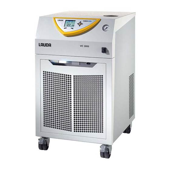
Device description 3.2 Design of the device Fig. 1: Front Filler nozzle with cover Control panel Manometer Mains switch Alarm output (interface 12N) and module slots Front panel (ventilation openings only on air-cooled devices) Ventilation openings (on both sides) Four castors (front castors with locking brakes) Variocool... - Page 16 Device description Fig. 2: Rear VC 5000 W Pump connection, outlet Bypass adjustment wheel Pump connection, inlet Drain tap Connection nozzle for water cooling return (only present on water-cooled devices) Connection nozzle for water cooling inlet (only present on water-cooled devices) Ventilation grid Type plate Mains cable...
-
Page 17: Operating Elements
Device description Control panel Fig. 3: Control panel Light sensor Manometer Mains switch ENTER button and arrow buttons Softkeys (left and right) USB interface Type B (on the side of the control panel) TFT display 3.3 Operating elements 3.3.1 Mains switch VC 3000 (W) and lower The mains power switch can be toggled between the following positions:... -
Page 18: Functional Elements
Device description The UP, DOWN, RIGHT and LEFT arrow buttons can be used to navigate in the screen. A selection in the screen can be confirmed with the ENTER button. You can control can buttons functions shown in the display with the soft keys. -
Page 19: Interfaces
9-pin SUB-D socket. Galvanically separated by an optocoupler. The RS 232 interface can be connected directly with the PC using a straight-through cable. The LAUDA command set makes the interface module compatible with the product lines ECO, Variocool, Proline, Proline Kryomat, PRO, Integral XT and Integral T. -
Page 20: Equipment
LRZ 923) with connection via RJ45 sockets. EtherCAT is an Ethernet-based field bus with master-slave functionality. Detailed information for the connection and use of these interfaces can be found in the operating manual of the respective LAUDA interface module. 3.5 Equipment Heater A heater can be installed in all devices if required. - Page 21 Depending on the increase in pump power, this option reduces the cooling capacity by more than 200 W. It also results in greater device installation height for the VC 1200 (W) and VC 2000 (W) devices. The installation of a more powerful pump is only available ex factory.
-
Page 22: Type Plate
Device description 3.6 Type plate The type plate information is explained in detail in the following table. Certain information is dependent on installed equipment. Specification Description Type Device type Catalogue No. Catalogue number of the device Serial No. Serial number of the device Refrigerant I Refrigerant that is used in the cooling unit of the device... -
Page 23: Before Starting Up
Before starting up Before starting up 4.1 Placement Very specific placement conditions are applicable to the devices. These placement conditions are mainly specified in the technical data for the device. Further information about the technical data can be found at Ä Chapter 11.1 ‘General data’ on page 93. Additional placement conditions are described below. -
Page 24: Connecting The Consumer
Before starting up Lock the castors on the device. Push the lever downwards to lock them. Attach the "Hot surface" warning sticker in a clearly visible position for applications above 70 °C. 4.2 Connecting the consumer CAUTION! Bursting of the external consumer Scalding, frostbite ... -
Page 25: Connecting External Consumer
°C in mm standard) VC 1200 to VC EPDM hose with 5000 (W) Hose nozzle with fabric reinforce- 10 bar 19 x 27 -40 – 100 RKJ 032 screw cap EOA 004 G ¾... -
Page 26: Cooling Water
Before starting up Note the following: To prevent damage to the consumer, fully open the bypass adjustment wheel on the rear of the device. To do so, turn the adjustment wheel anticlockwise. Temperature control hoses: Always use the largest possible diameters and shortest possible tube lengths in the external liquid circuit. - Page 27 Before starting up Seawater is not suitable due to its corrosive properties and will result in corrosion in the cooling water circuit. Water containing iron and iron particles in the water lead to cor- rosion in the cooling water circuit. Hard water is not suitable for cooling due to the high lime con- tent resulting in calcification in the cooling water circuit.
-
Page 28: Connecting Cooling Water
Description Value Maximum cooling water 10 bar pressure Differential pressure 1 – 6 bar VC 1200 W and VC 2000 W cooling water rp 3 – 6 bar VC 3000 W and greater Cooling water tem- approx. 15°C recommended, perature 10 –... -
Page 29: Installing The Driver For The Standard Usb Interface
Before starting up Fig. 7: Flange connector (front) in idle state Normally open contact Centre Normally closed contact Front view of the flange connector or of the coupling socket on the solder side Idle state The alarm output is in resting state: ... -
Page 30: Connecting Device To A Pc
A special USB driver must be installed on your PC to be able the USB interface of the constant temperature equipment to respond. The LAUDA company makes the USB Virtual COM Port driver available for download at http://www.lauda.de. Supported operating systems are Windows XP SP3, Windows Vista, Windows 7, Win- dows 8 and Windows 10 (each with 32 bit and 64 bit). -
Page 31: Installing Modules
Before starting up 4.4.4 Installing modules Devices can be optionally supplemented with additional interface modules. These can be installed in two different size module slots on the front of the device. Right module slot (approx. 51 mm x 27 mm) for RS232 / RS485 module / analogue module / contact modules / Profibus module Left module slot (approx. - Page 32 Before starting up The following information refers to the Ethernet‑ as well as the RS 232/485‑interfaces. Command Meaning IN_PV_00 Query of the bath temperature (outlet temperature) IN_PV_01 Query of controlled temperature (internal/external, Pt/external, analogue/ external serial) IN_PV_03 Query of external temperature T (Pt100).
- Page 33 Before starting up Command Meaning IN_DO_02 Status of contact input 2: 0 = normally open switch open / 1 = normally open switch closed IN_DO_03 Status of contact input 3: 0 = normally open switch open / 1 = normally open switch closed IN_MODE_00 Keyboard: 0 = free / 1 = blocked...
-
Page 34: Write Commands Of Serial Interfaces
Before starting up Command Meaning RMP_IN_01 Query of the current segment number RMP_IN_02 Query of the set program loops RMP_IN_03 Query of the current program loop RMP_IN_04 Query of which program additional commands refer to RMP_IN_05 Query of which program is currently running (0 = none) LOG_IN_00_XXXX Query of a measuring point XXXX from data logger (response: e. - Page 35 Before starting up The following information refers to the Ethernet‑ as well as the RS 232/485‑interfaces. Command Meaning OUT_PV_05_XXX.XX Specifying external temperature via interface OUT_SP_00_XXX.XX Setpoint transfer with max. 3 digits before the decimal point and max. 2 digits afterwards OUT_SP_02_XXX State cooling (0 = OFF / 1 = ON / 2 = AUTOMATIC) OUT_SP_04_XXX...
-
Page 36: Error Messages From The Constant Temperature Equipment To The Control Centre
Before starting up Command Meaning RMP_START Starts programmer RMP_PAUSE Stops programmer RMP_CONT Starts programmer again after hold RMP_STOP Stops the program RMP_RESET Deletes program (all segments) RMP_OUT_00_XXX.XX_XXX Sets the programmer segment (temperature, time, tolerance and pump XX_XXX.XX_X level). A segment is added and allocated the appropriate values. RMP_OUT_02_XXX Number of program cycles: 0 = infinite / 1–250 Please note:... -
Page 37: Cable And Test Of Interface Rs 232
Before starting up Error Description ERR_2 Incorrect input (e.g. buffer overflow) ERR_3 Incorrect command ERR_5 Syntax error in the value ERR_6 Impermissible value ERR_8 Module or value not available ERR_30 All segments of the programmer are occu- pied ERR_31 Setpoint input not possible, analogue set- point input is set to ON. -
Page 38: Protocol Rs 232
Before starting up Please note: Use shielded connection cables. Connect shield to connector case. The cables must be galvanically isolated from the rest of the electronics. Do not connect unassigned pins. The RS 232 interface can be easily checked on a connected PC with the Microsoft Windows operating system. -
Page 39: Connecting Cable Rs 485
Before starting up 4.4.10 Connecting cable RS 485 Connection RS 485 Thermostat with 9-pin Sub-D socket Contact Data Data A (-) SG (Signal Ground) optional Data B (+) Please note: Use shielded connection cables. Connect shield to connector case. The cables must be galvanically isolated from the rest of the electronics. -
Page 40: Commissioning
Observe the safety data sheet of the heat transfer liquid. You can request the safety data sheets of the heat transfer liquid at any time if required. Tab. 6: Approved heat transfer liquids Viscosity LAUDA Tem- Viscosity Container size Chemical (kin) in mm²/s... -
Page 41: Establishing Power Supply
Commissioning The water must be free of impurities. Water containing iron is unsuitable due to rust formation and untreated river water is unsuitable due to algae formation. The addition of ammonia is not permitted. 5.2 Establishing power supply Personnel: Operating personnel NOTICE! Use of unauthorised mains voltage or mains fre- quency... -
Page 42: Switching On Device For The First Time And Filling With Water
Commissioning 5.3 Switching on device for the first time and filling with water 5.3.1 Fill mode If the filling mode is active, the words " filling mode " appear on a yellow background in the basic window. The device does not heat or does not cool. The device has a program for convenient filling with heat transfer liquid. -
Page 43: Switching On And Filling Device
Commissioning 5.3.2 Switching on and filling device Personnel: Operating personnel Protective equipment: Protective goggles Protective clothing Protective gloves WARNING! Overflow of heat transfer liquid Electric shock Do not overfill the machine. Note the level indicator and the thermal volume expansion of the heat transfer liquid. - Page 44 Commissioning The window for selection of the menu language is displayed on the screen. Select the required menu language using the UP and DOWN arrow buttons. Confirm your selection with the OK button. For example, select [Deutsch] to see display entries in the German language.
-
Page 45: Setting Pump Pressure
Commissioning Operation outdoors at outdoor temperatures below 5 °C A warning is displayed on the screen indicating the duration of the preheating time for the compressor and whether the compressor needs preheating. Increased wear or damage to the compressor may result if the compressor is not preheated! Further information can be found at Ä... -
Page 46: Operation
Operation Operation 6.1 General safety instructions CAUTION! Bursting of the external consumer Scalding, frostbite A bypass regulator is available to set the pump pressure. CAUTION! Overheating beyond maximum operating tem- perature in the event of a fault Burns, scalding ... - Page 47 Operation Fig. 13: Menu structure part 1 Variocool...
- Page 48 Operation Menu structure for Graph, Clock and Standby Fig. 14: Menu structure part 2 Variocool...
-
Page 49: Switching On The Device
Operation 6.4 Switching on the device Personnel: Operating personnel Switch on the device using the mains power switch. A signal tone sounds. The basic window is displayed. After switching on, the device defaults to the standby operating mode if the start operating mode is not set to on . - Page 50 Operation External actual temperature Text (depending on set control var- iable, the internal actual temperature Tint is also displayed here) Setpoint temperature Tset Fig. 18: Status display Softkey button, left Enter button Softkey button, right The functions of the softkeys and the function of the Enter button are shown in this bar.
-
Page 51: Menu Window
Operation 6.5.2 Menu window Navigating to the main menu You can perform the following steps to reach the main menu: Press the ENTER button in the basic window. If you are in a submenu, you can return to the main menu with the left arrow button. -
Page 52: Input Window
Operation Navigation in the menus You have the following options: Use the UP and DOWN arrow buttons to navigate between the menu items. Press the RIGHT arrow button to select a submenu. Press the LEFT arrow button to return to a previous menu. -
Page 53: Lock And Release Operating Buttons
Operation 6.5.4 Lock and release operating buttons The operating buttons can be locked in order to protect the device when using a process control system or against unauthorized access. Lock the operating button Personnel: Operating personnel Change to the main menu. Press and hold down the [ENTER] button. -
Page 54: Specifying The Set Point
Operation Personnel: Operating personnel Change to the main menu. Select the menu item Setup Temp. limits. Select one of the following options: Select the first entry Til to set the lower limit value. Select the second entry Tih to set the upper limit value. Fig. -
Page 55: Smartcool (Cooling)
Operation Personnel: Operating personnel Press the [Standby] softkey button. The device is in the standby operating mode. The Standby entry in the softkey bar is highlighted. This operating mode is also shown in the expanded status dis- play. Press the Standby softkey button to activate the Operation operating mode. -
Page 56: External Control
Operation 6.10 External control 6.10.1 Activating external control Personnel: Operating personnel Select the menu item Control Variable extern Pt100 in the Control menu. This option is only available if a Pt100 module for an external temperature sensor has been con- nected. -
Page 57: Control
Operation Specifying offset source Personnel: Operating personnel Select the menu item Offset source in the Setpoint offset menu. Select one of the following options: You deactivate the setpoint offset using off . You can select the appropriate source with the other menu items. -
Page 58: Basics
Operation 6.11.1 Basics Explanation of terms Control - Output value of the controller to compensate for the dif- value ference of actual value to setpoint (control deviation). - The PID controller operates very precisely and consists con- of P, I and D parts. troller Propor- - The proportional range Xp specifies the temperature... - Page 59 Operation Indications of incorrect settings The picture on the left shows optimum setting of the control param- eters. Fig. 35: Optimum setting If the Xp parameter is selected too large, the actual value reaches the proportional range early and the P part becomes smaller than 100% of the control value.
-
Page 60: Calling The Control Menu
Operation In this case shown, the I part is set too large (parameter Tn too small). The I part integrates the control deviation until this becomes 0. If this integration runs too quickly, the control value, i.e. the output signal of the controller, is too large. This results in (dimin- ishing) oscillations of the actual value around the setpoint. -
Page 61: Overview Of Internal Control Parameters
Operation 6.11.3 Overview of internal control parameters The internal control compares the setpoint temperature with the outflow temperature and calculates the actuating signal, i.e. the amount to be heated or cooled. Tab. 7: The following control parameters can be adjusted for internal control: Parameter Description... -
Page 62: Overview Of External Control Parameters
Operation Confirm with the OK button. Selection of the menu item Tv manual/auto activates manual or automatic adjustment of the parameters depending on the previous setting. An input window is displayed when the other menu items are selected. The respective value can be adjusted within the displayed limits. -
Page 63: Adjusting External Control Parameters
Operation The temperature limits Tih and Til also influence the control. 6.11.6 Adjusting external control parameters Personnel: Operating personnel Select the menu item Control Parameter extern Pt100 in the Control menu. Select one of the following options: You can select any of the listed control parameters. With Tv manual/auto , you can define whether the control parameters Tve , Tde and Prop_E are set manually or automatically. -
Page 64: Setting Display Brightness
Operation Personnel: Operating personnel Change to the main menu. Select the menu item Setup Basic setup Sounds. Select one of the options depending on which sound you want to adjust. Select a volume level. Confirm with the OK button. Fig. -
Page 65: Limiting Current Consumption
Operation Personnel: Operating personnel Change to the main menu. Select the menu item Setup Basic setup Autostart. Select one of the following options: With off , the device is in the standby operating mode after a mains power failure. Normal operation is continued directly after a power failure using on . -
Page 66: Configuring Alarm Level For Fill Level
Operation 6.12.6 Configuring alarm level for fill level A warning about low level of the device is usually output on the device starting from the second level stage. However, the alarm level before low level can be configured within a specific range. Personnel: Operating personnel Change to the main menu. -
Page 67: Entering The Offset Of The Internal Actual Temperature (Calibration)
Operation Personnel: Operating personnel Change to the main menu. Select the menu item Setup Basic setup Language. Select any of the available languages. Confirm with the OK button. Fig. 49: Selecting menu language 6.13 Entering the offset of the internal actual temperature (calibration) The factory calibration is overwritten during the adjust- ment. -
Page 68: Restoring Factory Settings
Operation Personnel: Operating personnel Change to the main menu. Fig. 51: Factory calibration setting Select the menu item Setup Calibration Factory Calibration. Select one of the following options: Selecting no returns to the previous display without making any changes. Selecting yes restores the factory calibration. -
Page 69: Device Status
Operation Select the appropriate menu item in the parameter list. The internal and the external control parameters can be reset using Control parameter . The settings for the internal sensor can be reset with internal Pt1000 . Setpoint and maximum current consumption can be reset with miscellaneous . -
Page 70: Read Errorstore
Operation 6.16.2 Read Errorstore The devices have an Errorstore for error analysis. Up to 140 warning, error and alarm messages can be stored in the Error- store. Select the menu item Errorstore in the Device Status menu. The latest message is in the first position. The message text is displayed in the footer. -
Page 71: Displaying Device Type
Operation Personnel: Operating personnel Select the menu item SW version in the Device Status menu. The corresponding software versions are displayed depending on device type and connected modules. Fig. 59: Software version 6.16.5 Displaying device type The device type is shown directly at the menu item Type in the Device Status menu. - Page 72 Operation Possible settings Setting Description Segment number of the program Tend End temperature to be reached Time in hours (hh) in which the specified temperature should be reached. Time in minutes (mm) in which the specified temperature should be reached Tolerance The tolerance defines the level of accuracy with which the end temperature should be...
- Page 73 Operation ____ 70.00 60.00 30.00 A new segment with the number 3 was entered in the edited table. The time for the segment with number 4 was also changed. The tolerance for the segment with number 5 was adjusted. Tab. 11: "After" table (- - - -, edited) Tend Start...
-
Page 74: Selecting A Program
Operation The tolerance field enables precise adherence to the delay time at a specific temperature. Only once the actual tem- perature of the tolerance range has been reached (1), will the following segment be processed so that e.g. the ramp of the second segment will not be started until after a delay of 2. - Page 75 Operation Personnel: Operating personnel Select the menu item Edit for the selected program. You can now edit the segments. Fig. 64: Editing program Editing segments Personnel: Operating personnel Note the following: No time specification is possible in the starting segment. The temperature of the first segment is reached as quickly as pos- sible to change to segment 2 after reaching the set tolerance.
- Page 76 Operation Inserting a new segment Personnel: Operating personnel Navigate to the segment below which the new segment should be inserted. Navigate to the No. column in this segment. Press ENTER. A new segment is created. Fig. 65: Selecting program segments Deleting a segment Personnel: Operating personnel...
-
Page 77: Defining Program Loops
Operation The currently running program opens. You can now edit the segments of the currently running pro- gram. Fig. 66: running program Completing editing Personnel: Operating personnel When you have completed the program, you can return to the program overview with the LEFT arrow button. 6.17.4 Defining program loops Personnel:... -
Page 78: Starting, Interrupting And Ending A Program
Operation 6.17.5 Starting, interrupting and ending a program Personnel: Operating personnel Select the Status menu item for the selected program. Fig. 69: Setting program status You have the following options: Select the Start option to start the program. If the program is started, it can be interrupted using Pause . -
Page 79: Maintenance
Maintenance Maintenance 7.1 General safety instructions DANGER! Contact with live or moving parts Electric shock, impact, cutting, crushing The device must be disconnected from the mains power supply before any maintenance work. Repairs must only be carried out by specialists. DANGER! Heat transfer liquid drips onto the electronics Short circuit... -
Page 80: Cleaning Device
Maintenance Interval Maintenance work monthly Inspection the drain tap for leaks by visual inspection from the outside Inspection of the external hoses for material fatigue and leaks Inspection of the hose clips for correct and secure fit Inspection of the low level safety function (only for devices with heater) Cleaning of the condenser (only for air-cooled devices) Cleaning of the water filter (only for water-cooled devices) quarterly... -
Page 81: Cleaning Air-Cooled Condenser
Maintenance The liquid level in the device is shown on the display. Switch on the device. Set the target temperature to room temperature. Reduce the liquid level in the device. To do so, drain the heat transfer liquid via the drain tap. The display will show the heat transfer liquid level drop- ... -
Page 82: Decalcifying Cooling Water Circuit
Operating personnel Switch off the device using the mains power switch. Dissolve the decalcifying agent in a bucket of water. Decalcification requires LAUDA decalcifying agent (catalogue number LZB 126, 5 kg packaging). Read the safety instructions and the instructions for use on the packaging for handling the chem- ical. -
Page 83: Checking Heat Transfer Liquid
Switch on the device and adjust the setpoint to 10 °C. After starting the cooling unit, fill the device through the inlet hose of the water cooling unit with LAUDA decalcifying agent. Use a funnel or a pump. Continuously fill in decalcifying agent or pump it around. Con- tinue this process until the foaming reaction goes down. -
Page 84: Faults
LAUDA Constant Temperature Equipment service. Contact details can be found in Ä Chapter 13.4 ‘LAUDA contact’ on page 102. Errors are displayed with the appropriate description and an error code in the form of a sequential number. -
Page 85: Low Level Alarm
Faults Code English output Description Digital Input Fault at the digital input / switch contact T ext Ethernet No signal for actual value via the Ethernet module 8.3 Low Level alarm If the liquid level falls below the minimum level, an alarm sounds. -
Page 86: Warnings - Control System
Faults Restarting device Eliminate the cause of the error. After cooling down, lock the display using the OK button. The device restarts. 8.5 Warnings - control system All warnings of the control system start with the prefix 0. The prefix is followed by two additional digits. These digits are listed in the following table. -
Page 87: Warnings - Safety System
Faults Code English output Description SW Pump 2 old Software version of pump 2 too old SW Pump 3 old Software version of pump 3 too old SW HTC old Software version of high temperature cooler too old SW Ext. Pt100 old Software version of external Pt100 too old SW Ethernet old Software version of Ethernet too old... -
Page 88: Warnings - Smartcool
Faults Code English output Description SW Safety too old Software version of safety system too old SW Command too old Software version of command remote control unit too old SW Cool too old Software version of cooling module too old SW Analog too old Software version of analogue module too old SW Serial too old... - Page 89 Refrigerant unit does not run Valve not closed Valve of the cooling circuit does not close Configure EEV0 Contact LAUDA Service Configure EEV1 Contact LAUDA Service Preheat unit A warning concerning possible damage to the cooling system is sent when the device is operated below 5 °C.
-
Page 90: Decommissioning
Decommissioning Decommissioning 9.1 Draining device Personnel: Operating personnel WARNING! Contact with hot or cold heat transfer liquid Scalding, frostbite Bring the heat transfer liquid to room temperature before draining. Also note the following: Observe the regulations for disposal of the used heat transfer liquid. - Page 91 Decommissioning Personnel: Operating personnel Temper the device to approx. 20°C. Switch off the device. Close the cooling water inlet. Unscrew the cooling water hose at the inlet of the water cooling unit from the threaded connection neck. A water filter is located in the inlet connecting spigot of the water cooling unit.
-
Page 92: Disposal
Disposal Disposal 10.1 Disposing of refrigerant The refrigerant must be disposed of in accordance with Directive 2015/2067/EU in combination with 517/2014/EU. CAUTION! Uncontrolled escape of refrigerant Impact, cutting Disposal must be performed by specialist per- sonnel. NOTICE! Uncontrolled escape of refrigerant Environment ... -
Page 93: Technical Data
Unit °C °C VC 1200 -20 – 40 -20 – 80 ±0.05 450 x 550 x 650 VC 1200 W -20 – 40 -20 – 80 ±0.05 450 x 550 x 650 VC 2000 -20 – 40 -20 – 80 ±0.05... - Page 94 Technical Data The case height is 140 mm higher for the VC 1200 (W) and VC 2000 (W) devices with the more powerful pump. Clearance around the Exhaust air (air- Device device cooled devices) cm (front/back/right/left) m³/h VC 1200 20/20/20/20...
-
Page 95: Cooling Capacity
Cooling Cooling Cooling Cooling Cooling Device capacity capacity capacity capacity (20°C) capacity (0 °C) (10 °C) (-10 °C) (-20 °C) VC 1200 (W) 1.20 1.00 0.70 0.40 0.14 VC 2000 (W) 2.00 1.50 1.06 0.68 0.38 VC 3000 (W) 3.00 2.40... -
Page 96: Filling Volume And Characteristics Of The Pumps
Technical Data Unit VC 1200 VC 2000 VC 1200 W VC 2000 W 1397 1397 1397 1397 (100a) equivalent 0.70 0.81 0.70 0.81 Tab. 16 Unit VC 3000 VC 5000 VC 3000 W VC 5000 W Refrigerant R-449A R-449A R-449A... - Page 97 The pumps characteristics were determined using water as heat different mains supplies transfer liquid. Tab. 19: Maximum flow pressure and maximum flow rate Alternating current VC 1200 (W) VC 2000 (W) VC 3000 (W) 0.9 bar; 28 L/min 0.9 bar; 28 L/min 3.2 bar;...
- Page 98 Technical Data Characteristic curves of the pumps Fig. 77: Characteristic curves of the pumps Fig. 78: Characteristic curves of the pumps Variocool...
-
Page 99: Heater
Technical Data 11.5 Heater Tab. 20: Heat output and power consumption Alternating current VC 1200 (W) VC 2000 (W) VC 3000 (W) Unit 230 V; 50 Hz Heat output Power consumption with heater 200 V; 50/60 Hz Heat output Power consumption with heater 208–220 V;... -
Page 100: Equipment, Voltage-Independent
Insulation of the cooling Devices Sound insulation Outdoor installation water hydraulic system VC 5000 VC 7000 VC 10000 VC 1200 W VC 2000 W VC 3000 W VC 5000 W VC 7000 W VC 10000 W 11.7 Line fuse Alternating current... -
Page 101: Accessories
EQD 047 Tab. 26: Flow rate monitor Accessories for device Catalogue number Flow rate monitor G 3/4" VC 1200 (W) – 5000 (W) LWZ 118 Flow rate monitor G 1 1/4" VC 7000 (W) – 10000 (W) LWZ 119 Variocool... -
Page 102: General
13.2 Technical changes Manufacturer reserves right to make technical modifications. 13.3 Warranty conditions LAUDA provides a warranty of one year on equipment as standard. 13.4 LAUDA contact Contact LAUDA Service Constant Temperature Equipment in the following cases: In the event of faults on the device... - Page 103 General Variocool...
-
Page 104: Index
Index Index Warnings (safety system) ....87 Warnings (SmartCool) ....88 Accessories Condenser . - Page 105 Evaporator ......18 Expanded status display (display) ... . 50 LAUDA Service constant temperature equipment External consumer Address .
- Page 106 Example ......71 Service (LAUDA, Constant Temperature Equip- ment) ....... . . 102 Interrupting .
- Page 107 Index Install driver ......30 Soft key bar (display) ..... 50 Soft keys (position) .
- Page 108 S190000001 Types: VC 1200, VC 1200 W, VC 2000, VC 2000 W, VC 3000, VC 3000 W, VC 5000, VC 5000 W, VC 7000, VC 7000 W, VC 10000, VC 10000 W comply with all relevant provisions of the EC Directives listed below due to their design and type of construction in...
- Page 109 Product Returns and Clearance Declaration Product Returns Would you like to return a LAUDA product you have purchased to LAUDA? For the return of goods, e.g. for repair or due to a complaint, you will need the approval of LAUDA in the form of a Return Material Authorization (RMA) or processing number.
- Page 112 LAUDA DR. R. WOBSER GMBH & CO. KG Pfarrstrasse 41/43 ◦ 97922 Lauda-Königshofen ◦ Germany Phone: +49 (0)9343 503-0 ◦ Fax: +49 (0)9343 503-222 E-Mail: info@lauda.de ◦ Internet: https://www.lauda.de...
Need help?
Do you have a question about the VC 1200 and is the answer not in the manual?
Questions and answers
Hi. Please can you tell me what might cause a VC1200 pressure switch to activate (alarm code 304). My unit is showing this alarm and making a loud noise when pumping, it's also getting hot to touch.
Alarm code 304 activates when the pressure switch in the cooling circuit is triggered.
This answer is automatically generated