Lauda Microcool MC 250 Operation Manual
Circulation chillers
Hide thumbs
Also See for Microcool MC 250:
- Operating instructions manual (72 pages) ,
- Operation instructions manual (64 pages)

Related Manuals for Lauda Microcool MC 250


Summary of Contents for Lauda Microcool MC 250
- Page 1 Operation manual Microcool MC 250, MC 350, MC 600, MC 1200 Circulation chillers V7R6 Read this manual prior to performing any task!
- Page 2 Manufacturer LAUDA DR. R. WOBSER GMBH & CO. KG Laudaplatz 1 97922 Lauda-Königshofen Germany Telephone: +49 (0)9343 503-0 Fax: +49 (0)9343 503-222 E-mail: info@lauda.de Internet: https://www.lauda.de Translation of the original operation manual Q4DT-E_13-001, 7, en_US © LAUDA 2021 Replaces issue V6R17/16, V5R8, V5R7, V5R5, V4R13, V4R6, V3R20, V3R19, V3R17...
-
Page 3: Table Of Contents
External consuming unit............................. 23 4.2.1 Hoses................................. 23 4.2.2 Connecting an external consuming unit....................24 Commissioning..................................26 LAUDA heat transfer liquids............................. 26 Establishing a mains connection..........................27 Switching on the device and filling with heat transfer liquid................... 27 Microcool 3 / 57... - Page 4 Setting the pump pressure............................29 Operation....................................31 Switching on the device............................... 31 Basic display and menu items............................. 31 Indications in the display............................33 Setting the temperature set point..........................33 Restricting the temperature limits..........................34 Configuring the clock timer............................34 RS 232 interface................................. 37 6.7.1 Configuring the RS 232 interface......................
- Page 5 Refrigerant and filling charge............................51 11.4 Hydraulic circuit................................52 11.5 Voltage-dependent data............................52 General....................................53 12.1 Copyright..................................53 12.2 Technical changes............................... 53 12.3 Contact LAUDA................................. 53 12.4 Declaration of Conformity............................53 12.5 Product Returns and Clearance Declaration......................55 Index..................................... 56 Microcool 5 / 57...
-
Page 6: Safety
Be sure to carefully store this copy of the operating manual. If this operating manual is lost, contact LAUDA Service Constant Temperature Equipment. You will find the contact information here Ä... -
Page 7: Foreseeable Misuse
Any technical modification of the device by the user is prohibited. Any damage resulting from unauthorized modification is not covered by customer service or the product warranty. Service work may only be performed by the LAUDA Service department or a service partner authorized by LAUDA. Microcool 7 / 57... -
Page 8: Requirements For The Heat Transfer Liquid
LAUDA heat transfer liquids have been tested by the company LAUDA DR. R. WOBSER GMBH & CO. KG and approved for this device. The heat transfer liquids are suitable for a specific temperature range. -
Page 9: Personal Protective Equipment
1.11 Personal protective equipment Protective clothing Protective clothing is required for certain activities. This protective clothing must comply with the legal requirements for personal protective equipment. Protective clothing should have long sleeves. Safety footwear is additionally required. Protective gloves CE protective gloves are required for certain activities. These protective gloves must comply with the legal requirements for personal protective equipment of the European Union. - Page 10 Caution A warning of "caution" indicates a possibly dangerous situation. If this warning is not observed, then minor, reversible injury could occur. CAUTION! Type and source Consequences of not following instructions Measure 1 Measure... Notice A "notice" warns that dangers to property or the environment may exist. NOTICE! Type and source Consequences of not following instructions...
-
Page 11: Unpacking
Also notify LAUDA Constant Temperature Equip- ment Service department immediately. You will find the con- tact information here Ä Chapter 12.3 “Contact LAUDA” on page 53. Table 2: Accessories included as standard... -
Page 12: Device Description
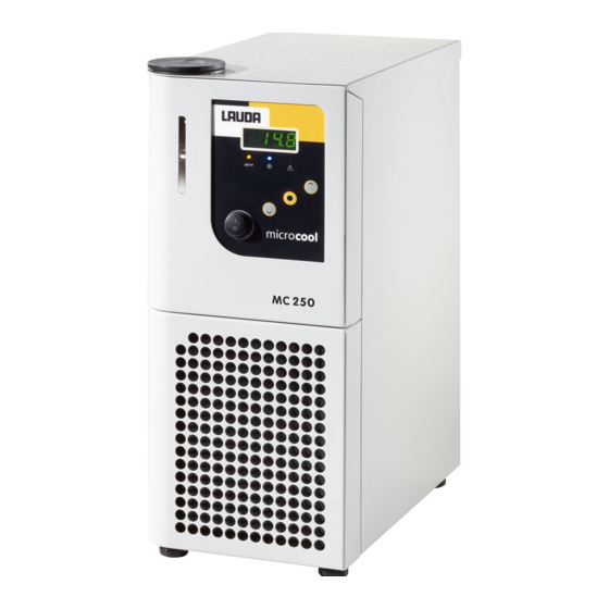
Device description Device types The names of the devices consist of the following components. Component Description Microcool <number>, e.g. 600 Indication of the cooling capacity in watts Available device types Device type Description MC 250 Air-cooled table-top device with a cooling capacity of 250 watts MC 350 Air-cooled table-top device with a cooling... - Page 13 Front of the MC 250 and MC 350 Fig. 1: Overview of the front (MC 350) Filler nozzle with cover Level indication Operating unit Front panel with ventilation openings Four feet Microcool 13 / 57...
- Page 14 Back of the MC 250, MC 350 Fig. 2: Overview of the back Overflow connection Pump connection, outflow Pump connection, return flow Rating label Alarm output RS 232 interface Power supply Drain screw Ventilation openings 14 / 57 Microcool...
- Page 15 Front of the MC 600, MC 1200 Fig. 3: Overview of the front Filler nozzle with cover Level indication Operating unit Pressure gage Front panel with ventilation openings Four casters with locking brake Microcool 15 / 57...
- Page 16 Back of the MC 600, MC 1200 Fig. 4: Overview of the back Pump connection, outflow Bypass adjusting wheel Pump connection, return flow Overflow connection Rating label RS 232 interface Alarm output Power supply Drain screw 10 Ventilation openings 16 / 57 Microcool...
-
Page 17: Operating Elements
Operating unit Display LEDs Display buttons Mains switch Fig. 5: Operating unit Operating elements 3.3.1 Mains switch The mains switch can be set to the following positions: Position [I] switches the device on. Position [O] switches the device off. 3.3.2 Display buttons Up arrow button Enter key Down arrow button... -
Page 18: Functional Elements
Functional elements 3.4.1 LEDs for function display yellow LED Blue cooling LED Red error LED Each device has three LEDs with the following functions: The yellow LED is lit if Kryo 30 is required as a heat transfer liquid. The blue cooling LED indicates whether the cooling unit is active. The red error LED is lit if the device has an error. -
Page 19: Pressure Gage
3.4.3 Pressure gage The device types with a bypass are equipped with a pressure gage for reading the set pump pressure. The pump pressure is regulated via the bypass adjusting wheel. The bypass adjusting wheel is located on the back of the device. -
Page 20: Interfaces
You will find technical data on the cooling unit in Ä Chapter 11.2 “Cooling unit” on page 51. 3.4.6 Interfaces Please note the following: The equipment connected to the extra-low voltage inputs and outputs must be reliably isolated from voltages dangerous to the touch in accordance with DIN EN 61140. -
Page 21: Rating Label
Rating label The specifications on the rating label are described in more detail in the following table. Certain specifications depend on the installed device options. These specifications are marked with a corresponding addendum. Specification Description Type Device type Catalog no. Catalog number of the device Serial no. -
Page 22: Before Starting Up
Before starting up Install device Special installation conditions apply to the devices. These installation condi- tions are specified for the most part in the technical data for the device. You will find further information on the technical data in Ä Chapter 11.1 “General data” on page 50. Additional installation conditions are described in the following. -
Page 23: External Consuming Unit
External consuming unit 4.2.1 Hoses CAUTION! Risk of heat transfer liquid escaping during operation due to the use of unsuitable hoses Cold burns Use hoses with a temperature resistance corresponding to the operating temperature range of the device. CAUTION! Contact with cold hoses Cold burns Use insulated hoses for temperatures below 0 °C. -
Page 24: Connecting An External Consuming Unit
Table 4: Hoses, insulated at the factory Clear Ø in Insulation thick- Temperature Catalog Type Pump connections Application area ness in mm range in °C number EPDM Devices with a max- Hose nozzle 13 mm, hose, insu- imum pump pres- -35 –... - Page 25 CAUTION! Risk of external hydraulic circuit bursting due to gage pressure Impacts, cutting, cold burns When laying the hoses, make sure they cannot kink. Please note the following: Temperature control hoses: Always use the largest possible diameters and shortest possible hoses in the external circuit. If the temperature control hose diameter is too narrow, the insufficient flow rate will cause a drop in temperature between the device and the external consuming unit.
-
Page 26: Commissioning
Commissioning LAUDA heat transfer liquids Please note the following: The heat transfer liquids each cover a recommended temperature range and must be suitable for the temperature range associated with their application. The heat transfer liquid becomes more viscous in the lower limit of the temperature range and affects temperature stability as well as the pump power and cooling capacity. -
Page 27: Establishing A Mains Connection
Establishing a mains connection Personnel: Operating personnel NOTICE! Use of impermissible mains voltage or mains frequency Device damage Compare the rating label with the available mains voltage and mains frequency. Please note the following: The mains plug disconnects the device from the power supply. The mains plug must be easy to identify and access. - Page 28 WARNING! Overflow of heat transfer liquid Electric shock Do not overfill the device. Observe the level display and the thermal volume expansion of the heat transfer liquid. WARNING! Spraying of heat transfer liquid Electric shock Do not spray heat transfer liquid. Use a funnel for filling. ...
-
Page 29: Setting The Pump Pressure
Fill level sufficient Switch on the device at the mains switch. A signal tone is emitted. The software version is shown in the display. The actual temperature is then shown in the display. The constant temperature equipment starts operation, the pump is started. - Page 30 Personnel: Operating personnel CAUTION! Risk of external consumer bursting Cold burns, impacts, cutting A bypass controller is provided to set the pump pressure (from MC 600). Use a safety valve for the protection of consuming units with a maximum permissible working pressure below the maximum pressure of the pump.
-
Page 31: Operation
Operation Switching on the device NOTICE! Overheating of the pump Device damage Never operate the device without heat transfer liquid. Personnel: Operating personnel Switch on the device at the mains switch. A signal tone is emitted. The software version is shown in the ... - Page 32 Fig. 11: Menu 32 / 57 Microcool...
-
Page 33: Indications In The Display
Indications in the display Basic display The basic display is the indication in the display which is shown unless other operations such as configuring settings are performed. The actual temperature of the device in °C is shown in the basic display. Fig. -
Page 34: Restricting The Temperature Limits
Press the input button to confirm. Restricting the temperature limits You must limit the temperature limit value range for safety reasons. These two values depend on the heat transfer liquid used. The default settings 45.0 °C and 5.0 °C are stored in the device and cannot be changed. Appropriate temperature limit values are: Aqua 90 - Set the range to the values 42 °C and 3 °C. - Page 35 Special features of the clock timer The clock timer is configured by a number of hours and minutes in the format hh.mm. The first two digits represent the number of hours, the last two represent the number of minutes. The clock timer can be set to a maximum of 99 hours and 59 minutes.
- Page 36 Configuring auto start CAUTION! Automatic device start with the auto start timer Cold burns, danger of injury, device damage Before using the auto start timer, ensure that all prepara- tory measures for intended use have been implemented! Select the menu item for specifying auto start. Press the input button to confirm.
-
Page 37: Rs 232 Interface
Switching on again manually If the device was switched to standby via auto shutdown and auto start has not been configured, the device can be switched on again manually. Press the Enter key to switch the device back on. This function is only available if auto start is not active. RS 232 interface 6.7.1 Configuring the RS 232 interface The baud rate for the RS 232 interface can be configured via the display. -
Page 38: Cable Test And Interface Test Of Rs 232
Terminal" is no longer part of the operating system. It is possible to communicate with the RS 232‑interface using the LAUDA control and application software, Wintherm Plus (catalog number LDSM2002). Terminal programs are available on the Internet as freeware. These pro- grams offer features similar to "HyperTerminal"... -
Page 39: Write Commands
6.7.4 Write commands Write commands are data specifications for the thermostat. Command Meaning OUT_SP_00_XXX.XX Set point transfer with a max. 3 places in front of the decimal point and a max. 2 places after OUT_SP_04_XXX [Hi] Outflow temperature limit upper value OUT_SP_05_XXX [Lo] Outflow temperature limit lower value START... -
Page 40: Error Messages
Command Meaning STATUS Query device status 0 = OK, -1 = fault STAT Query of fault diagnosis response: XXXXXXX; X = 0 no fault, X = 1 fault 1 character = error 2 characters = not assigned 3 characters = not assigned 4 characters = not assigned 5 characters = low level 6 characters = not assigned... -
Page 41: Interface Potential-Free Contact
Select the following option to output an electrical signal for alarms and errors. Fig. 21: Error and alarm option Select the following option to output an additional electrical signal for warnings. Wait approx. 4 seconds if you do not wish to accept the specified value. -
Page 42: Enter The Offset For The Temperature Probe
2-point calibration carried out with the menu item Cal . A calibrated reference thermometer (e.g. from the LAUDA DigiCal series) with the desired degree of accuracy is required. In other respects, the factory calibration should not be changed. - Page 43 Personnel: Operating personnel Select the menu item for restoring the factory setting. (Briefly) press the input button to confirm. Press and hold down the Enter key for about 3 seconds. donE appears in the display. The factory setting has been Fig.
-
Page 44: Maintenance
Maintenance General safety instructions DANGER! Contact with live or moving parts Electric shock, impacts, cutting, crushing The device must be disconnected from the mains power supply before any kind of maintenance is performed. Only skilled personnel are permitted to perform repairs. ... -
Page 45: Cleaning The Device
Cleaning the device Personnel: Operating personnel WARNING! Risk of cleaning agent entering the device Electric shock Only use a slightly damp cloth for cleaning. Please also note the following: Only use water and detergent to clean the control panel. Do not use acetone or solvent. -
Page 46: Faults
LAUDA Constant Temperature Equipment Service department. You will find the contact information in Ä Chapter 12.3 “Contact LAUDA” on page 53. Errors are symbolized with an E and a consecutive three-digit number. -
Page 47: Overview Of Alarms
Overview of alarms Alarms affect safety. The components of the device, such as the pump, switch off. The device emits a two-tone acoustic signal. In addition, the red LED on the device is lit. Output in the display Description In the case of a low-level alarm, the level of the heat transfer liquid is below the minimum limit. -
Page 48: Decommissioning
Decommissioning Draining the device Personnel: Operating personnel WARNING! Contact with cold heat transfer liquid Cold burns Bring the heat transfer liquid to room temperature before draining. Please also note the following: Observe the regulations for the disposal of used heat transfer liquid. Switch off the device. -
Page 49: Disposal
Disposal 10.1 Disposing of refrigerant Disposal of refrigerant must proceed according to regulation 2015/2067/EU in combination with regulation 517/2014/EU. CAUTION! Uncontrolled escape of refrigerant Impacts, cutting Never dispose of a cooling circuit that is still pressurized. Only specialized personnel are permitted to perform dis- ... -
Page 50: Technical Data
Technical data 11.1 General data The device sound pressure level is below 70 dB. According to EC Directive 2006/42/EC the sound pressure level of the devices is therefore not specified further. Specification Value Unit Installation Interior rooms Installation altitude above sea level up to 2,000 m maximum relative humidity of 80 % at 31 °C and Air humidity... -
Page 51: Cooling Unit
11.2 Cooling unit Table 10: Cooling capacity Unit MC 250 MC 350 MC 600 MC 1200 Cooling capacity (at 20 °C) 0.25 0.35 0.60 1.20 Cooling capacity (at 10 °C) 0.20 0.28 0.50 1.05 Cooling capacity (at 0 °C) 0.15 0.22 0.36 0.75... -
Page 52: Hydraulic Circuit
Unit MC 250 MC 350 MC 600 MC 1200 1430 1430 1430 1430 (100a) equivalent Table 14: Devices with 100 V; 50/60 Hz Unit MC 250 MC 350 MC 600 MC 1200 Refrigerant R-134a R-134a R-134a R-134a Maximum filling weight 0.092 0.095 0.31... -
Page 53: General
The manufacturer reserves the right to make technical modifications to the device. 12.3 Contact LAUDA Contact the LAUDA Service department in the following cases: Troubleshooting Technical questions Ordering accessories and spare parts Please contact our sales department for questions relating to your specific application. - Page 54 EC DECLARATION OF CONFORMITY Manufacturer: LAUDA DR. R. WOBSER GMBH & CO. KG Laudaplatz 1, 97922 Lauda-Königshofen, Germany We hereby declare under our sole responsibility that the machines described below Product Line: Microcool Serial number: from S210000001 Types: MC 250, MC 350, MC 600, MC 1200...
-
Page 55: Product Returns And Clearance Declaration
Product Returns and Clearance Declaration Product Returns Would you like to return a LAUDA product you have purchased to LAUDA? For the return of goods, e.g. for repair or due to a complaint, you will need the approval of LAUDA in the form of a Return Material Authorization (RMA) or processing number. -
Page 56: Index
Index Draining Device ....... 48 Accessories In series ....... 11 Adjustment (actual temperature) EMC . - Page 57 Interface ......20, 38 configure ......37 Safety notice Protocol .
- Page 60 Manufacturer LAUDA DR. R. WOBSER GMBH & CO. KG ◦ Laudaplatz 1 ◦ 97922 Lauda-Königshofen Telephone: +49 (0)9343 503-0 ◦ Fax: +49 (0)9343 503-222 E-mail: info@lauda.de ◦ Internet: https://www.lauda.de...
Need help?
Do you have a question about the Microcool MC 250 and is the answer not in the manual?
Questions and answers