Table of Contents
Advertisement
Advertisement
Table of Contents
Troubleshooting

Related Manuals for Uponor SYSTEMpro 311


Summary of Contents for Uponor SYSTEMpro 311
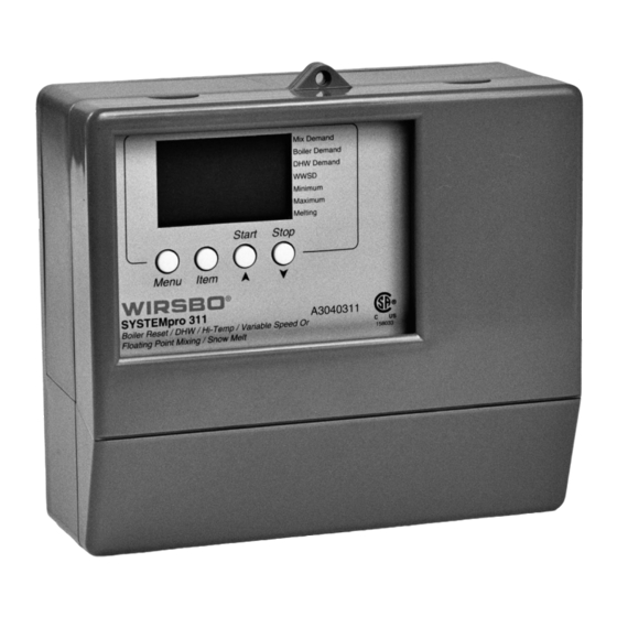
- Page 1 SYSTEMpro ™ Installation Manual...
- Page 2 SYSTEMpro ™ Installation Manual is published by Uponor Wirsbo 5925 148th Street West Apple Valley, MN 55124 (952)-891-2000 © 2002 Uponor Wirsbo, All rights reserved. First Edition First Printing July 2002 Printed in the United States of America...
-
Page 3: Table Of Contents
Step 1 – Checking Contents ..........14 If you are only INSTALLING Step 2 – The Control Base ..........15-17 the SYSTEMpro 311 go to: Step 3 – Rough-In Wiring............18 Step 4 – Attaching the Control to the Base ...... 19 INSTALLATION Step 5 –... - Page 4 Section G – Troubleshooting .......... 82-83 APPENDIX Variable Speed Injection Mixing......85-87 SYSTEMpro 311 Menu Tree ........88-89 III Application Drawings ..........90-97 IV Error Message Overview ........98-101 V SYSTEMpro 311 Program Setup ......102-103 INTRODUCTION - Table of Contents...
-
Page 5: Control Overview
As an added benefit, the SYSTEMpro 311 has the ability to control an indirect Domestic Hot Water (DHW) storage tank and a semi-automatic snow melt zone. -
Page 6: Navigating The Control
INTRODUCTION NAVIGATING THE CONTROL The SYSTEMpro 311 (also referred to as "control") has Mix Demand View Adjust Boiler Demand a Liquid Crystal Display (LCD) that lets users setup the DHW Demand min hr WWSD Misc operation of the system. The SYSTEMpro 311 has four... - Page 7 Display Item Field Numbers Field Displays an abbreviated Displays the current value name of the selected item of the selected item Mix Demand View Adjust Boiler Demand Menu DHW Demand Field min hr WWSD Misc Displays the current menu Minimum Open Close Maximum...
- Page 8 Access Levels • The SYSTEMpro 311 comes with four Access Level settings • Access Levels restrict the number of Items and Adjustments that can be accessed by the user • The access level of the control is found in the Miscellaneous...
-
Page 9: Viewing The Status Of The System Performance
INTRODUCTION VIEWING THE STATUS OF THE SYSTEM PERFORMANCE Mixing Reset Mode • The View Menu is available for viewing the current status of the system performance • By selecting the View Menu, and then pushing the item button, you can scroll through the available menu items showing the current settings and temperatures in the system OUTDOOR (See fig. - Page 10 SLAB (See fig. d) Actual slab temperature as read by the slab sensor S7 (MIX 10K) View NOTE: This screen will be available in the View Menu only when the Slab (SLAB) sensor is selected under the MIX 10K screen in the ADJUST Menu. Access Level USER INST...
- Page 11 Boil SUP (See fig. h) Shows actual boiler supply water temperature at boiler supply View sensor S3 location Access Level USER INST DHW TRG (See fig. i) The targeted DHW tank temperature the control has calculated View in order to meet the current DHW demand. NOTE: This screen will be available in the View Menu only when a DHW device is selected in Access Level...
-
Page 12: Snow Melt Mode
INTRODUCTION VIEWING THE STATUS OF THE SYSTEM PERFORMANCE Snow Melt Mode • The View Menu is available for viewing the current status of the system performance • By selecting the View Menu, and then pushing the item button, you can scroll through the available menu items showing the current settings and temperatures in the system OUTDOOR (See fig. - Page 13 MIX TRG (See fig. e) The targeted mixed supply water temperature the control has View calculated in order to meet current conditions Access Level USER INST MIX SUP (See fig. f) Shows actual mix supply water temperature to the system at View mix supply sensor S1 location Access Level...
-
Page 14: Viewing The Status Of The System Performance
Boil SUP (See fig. i) Shows actual boiler supply water temperature at boiler supply View sensor S3 location. Access Level USER INST DHW TRG (See fig. j) The targeted DHW tank temperature the control has calculated View in order to meet the current DHW demand. This screen is available only when a sensor is selected in the DHW SENS screen in the ADJUST Menu. -
Page 15: Installation
INSTALLATION TABLE OF CONTENTS Step 1 – Checking Contents ..........14 Step 2 – The Control Base ..........15-17 Step 3 – Rough-In Wiring............18 Step 4 – Attaching the Control to the Base ...... 19 Step 5 – Mounting the Sensors ........20-22 Step 6 –... -
Page 16: Step 1 - Checking Contents
INSTALLATION - STEP 1 CHECKING CONTENTS Check the contents of this package. CAUTIONS AND The Wirsbo SYSTEMpro 311 should have: DISCLAIMERS Failure to install and/or One SYSTEMpro 311 operate this control (A3040311) properly could result in: • Damage to the equipment •... -
Page 17: Step 2 - The Control Base
INSTALLATION - STEP 2 THE CONTROL BASE Removing the Control from the Base Press down at the fingertip grips on top of the front cover and pull out and down. (See fig. a) Lift the front cover up and away from the control. (See fig. - Page 18 Remove the safety dividers from the wiring chamber by pulling them straight out of their grooves. (See fig. e) Press the control release clip on the base inside the wiring chamber and slide the control upwards. (See fig. f) Release Clip The control lifts up and away from the base.
- Page 19 The control can also be mounted on a standard DIN rail. (See fig. i) First remove the control from its base and then, using the hooks and spring clip on the back of the control (ordered separately), mount it onto the DIN rail. This will be a popular option for those who prefer to mount the control inside a larger electrical panel.
-
Page 20: Step 3 - Rough-In Wiring
INSTALLATION - STEP 3 ROUGH-IN WIRING Things to note before you start wiring: • All electrical wiring should end in the control base wiring CAUTION chamber • The base has standard 7/8” (22 mm) knockouts All wiring must be • Knockouts accept common wiring hardware and conduit performed by a licensed fittings professional and comply... -
Page 21: Step 4 - Attaching The Control To The Base
INSTALLATION - STEP 4 ATTACHING THE CONTROL TO THE BASE 1) Push the SYSTEMpro 311 control into the base you mounted in Step 2 2) Slide the control down until it snaps firmly into place (See fig. a) INSTALLATION - Step 4 - Attaching the Control to the Base... -
Page 22: Step 5 - Mounting The Sensors
INSTALLATION - STEP 5 MOUNTING THE SENSORS Outdoor Sensor (S4) (See fig. a) The Outdoor Sensor includes a 10 kΩ thermistor which provides an accurate measurement of the outdoor temperature. The sensor is protected by a white U.V. resistant PVC plastic enclosure. Step One –... - Page 23 Universal Sensors (S1, S3, S5 & S6) (See fig. d) These Universal Sensors have a zinc sleeve for fast response and a wide operating range. They can be used in a multitude of applications. They are supplied with 10 inches (250 mm) of 2 conductor wire.
- Page 24 Slab Sensor (S7) (See fig. h) The Slab Sensor has a PVC plastic sleeve which is designed for use in soils or concrete. It is supplied with 20 ft (6 m) of 2 conductor cable. Step One – Mounting (See fig. i) NOTE: Proper placement of this sensor is critical for correct operation of the control.
-
Page 25: Step 6 - Electrical Connections To The Control
INSTALLATION - STEP 6 ELECTRICAL CONNECTIONS TO THE CONTROL IMPORTANT: Test to be certain no voltage is present in any wires. 120 VAC Powered Input Connections 120 VAC Power (See fig. a) • Provides power to microprocessor and control display as well as power to Boil P3 terminal (8) from Power L terminal (7) •... -
Page 26: Output Connections
• Use terminals as switch to make or break the boiler circuit • When the SYSTEMpro 311 requires the boiler to fire, contact closes between terminals 15 and 16 2) DHW Pump/Valve Contact (See fig. f) DHW P6/Vlv terminals (13 and 14) are an isolated output. - Page 27 6) Variable Speed Injection Pump (Cls/P4) (See fig. j) The SYSTEMpro 311 can vary the speed of a pump motor with locked rotor current of less than 2.4 A (most small wet rotor circulators may be used as described in APPENDIX I - page 85).
-
Page 28: Sensor Connections
Sensor Connections (8-13) WARNING: Do not apply power to these terminals as this will damage the control. Connect the two wires from sensors to terminals described below: 8) Outdoor Sensor S4 wires to Com and Out terminals (27 and 29) (See fig. l) •... -
Page 29: Unpowered Input Connections
Snow Melt Enable to Com terminal (27) on SYSTEMpro 311 • Connect the tN2 terminal from Remote Display Module or Snow Melt Enable to the tN2 terminal (30) on SYSTEMpro 311 INSTALLATION - Step 6 - Electrical Connections to the Control... -
Page 30: Temperature Resistance Chart
INSTALLATION - Step 6 - Electrical Connections to the Control... -
Page 31: Step 7 - Testing The Wiring
INSTALLATION - STEP 7 TESTING THE WIRING NOTE: The following tests are to be performed using standard testing practices and procedures. They should only be carried out by properly trained and experienced installers. Things to note before you start ANY testing: •... -
Page 32: Test The Power Supply
Test the Power Supply 1) Make sure exposed wires and bare terminals are not in contact with other wires or grounded surfaces 2) Turn on the power and measure the voltage between the Power L and Power N terminals (6 and 7) using an AC voltmeter, the reading should be between 108 and 132 VAC Test the Powered Demand Inputs Voltage Readings for ALL Demand Devices... - Page 33 Boiler Demand Pump (Boil Dem Pmp P7) — terminals (9 and 10) (See fig. b) 1) Make sure power to the pump circuit is off 2) Install a jumper between terminals (9 and 10) 3) When pump circuit is powered up, boiler demand pump should start 120 VAC Mixing System Pump (Mixing Pmp P1) —...
- Page 34 Mixing Valve Actuator — connected to Pwr Mix, Opn and Cls/P4 terminals (17, 18 and 19) STEP 1: (See fig. g) • Make sure power to the motor circuit is off 24 or 120 VAC • Install a jumper between the Pwr Mix and Opn terminals (17 and 18) •...
-
Page 35: Step 8 - Completing The Installation
INSTALLATION - STEP 8 COMPLETING THE INSTALLATION Once you have successfully tested all of the wiring and found that everything is operational, you are ready to complete the installation. 1) Make sure all power to the devices and terminal blocks is off, and remove any remaining jumpers from the terminals 2) Reconnect the terminal blocks to the control by carefully aligning them with their respective headers on the control... -
Page 36: Programming
PROGRAMMING TABLE OF CONTENTS Step 1 – Programming the Control ......35-55 DIP Settings ..........35-36 Programming the "Misc" Menu ....37 Programming the "Adjust" Menu.... 38-55 A. Boiler/High Temp Zone Settings..38-41 B. DHW Settings........42-43 C. Mixing Device Settings....44-49 D. -
Page 37: Step 1 - Programming The Control
For more detailed functions of any particular item, please refer to the Control Overview Section. IMPORTANT (PLEASE READ): The SYSTEMpro 311 is now fully installed and ready for a trained, qualified individual to begin entering the settings that will help it control a hydronic radiant heating system at its most efficient level. - Page 38 Lock/Unlock DIP Switch Setting (Factory Setting is Unlock) • Lock/Unlock DIP switch is used to lock and unlock the access (See fig. a) level of the control • In locked mode, access levels cannot be changed • A small icon representing a padlock is shown in the bottom right hand corner of the display, indicating if control is locked Snow Melting (See fig.
-
Page 39: Programming The "Misc" Menu
PROGRAMMING THE “MISC” MENU UNITS (See fig. a) 1) Go to UNITS item field in Miscellaneous (MISC) Menu 2) Select the temperature measurement units you wish all temperatures to be displayed in RANGE: °F, °C Misc DEFAULT: °F Access Level Misc BACKLITE (See fig. -
Page 40: Programming The "Adjust" Menu
PROGRAMMING “ADJUST” MENU A. BOILER / HIGH TEMP ZONE SETTINGS PROGRAMMING - Step 1 - Programming the Control... - Page 41 OUTDOOR DESIGN (OUT DSGN) (See fig. a) 1) Go to OUT DSGN item field in Adjust Menu Adjust 2) Set to the outdoor design temperature used in the heat-loss calculation RANGE: -60 to 50°F (-51 to 10°C) Access Level DEFAULT: 10°F (-12°C) USER INST BOILER ROOM (Boil ROOM) (See fig.
- Page 42 BOILER DESIGN (Boil DSGN) (See fig. d) 1) Go to Boil DSGN item field in Adjust Menu Adjust 2) Set to the design supply water temperature calculated in the heat-loss to satisfy the boiler/high temp zones RANGE: 70 to 220°F (21 to 104°C) Access Level DEFAULT: 190°F (88°C) USER...
- Page 43 WARM WEATHER SHUT DOWN (WWSD) (See fig. g) Adjust The control enters into WWSD when slab and outdoor temperatures exceed MELTING temperature by more than 1.5°F (1°C). Access Level 1) Go to WWSD item field in the Adjust Menu USER 2) Set to an outdoor temperature at which the system no INST longer needs to heat the zone to maintain a comfortable...
-
Page 44: Dhw Settings
PROGRAMMING “ADJUST” MENU B. DHW SETTINGS PROGRAMMING - Step 1 - Programming the Control... - Page 45 DHW DEVICE (DHW THRU) (See fig. h) 1) Go to DHW THRU item field in Adjust Menu 2) Select the type of DHW device you are using to supply flow to the heat exchange in the DHW tank Adjust Adjust RANGE: NONE, PUMP, VALV DEFAULT: PUMP Adjust...
-
Page 46: Mixing Device Settings
PROGRAMMING “ADJUST” MENU C. MIXING DEVICE SETTINGS (DIP set to Mixing Reset) PROGRAMMING - Step 1 - Programming the Control... - Page 47 MIXING ROOM (MIX ROOM) (See fig. l) 1) Go to MIX ROOM item field in Adjust Menu Adjust 2) Set to the desired room temperature for mixing zones NOTE: There is only a ±3°F (±1°C) Access Level adjustment in the LTD Access Level. USER INST DIP SETTING: Mixing Reset...
- Page 48 SLAB MINIMUM (SLAB MIN) (See fig. n) 1) Go to MIX 10K item field in Adjust Menu Adjust 2) Set MIX 10K to SLAB 3) Go to SLAB MIN item field in Adjust Menu 4) Set the minimum allowed core temperature of slab as long Access Level as the control is not in WWSD USER...
- Page 49 MIXING INDOOR (MIX INDR) (See fig. q) 1) Go to MIX INDR item field in Adjust Menu Adjust 2) Set to the room temperature used in original heat-loss calculations for the building (Normally 65 to 70°F) DIP SETTING: Mixing Reset Access Level RANGE: 35 to 100°F (2 to 38°C) USER...
- Page 50 MIXING MAXIMUM (MIX MAX) (See fig. s) 1) Go to MIX MAX item field in Adjust Menu Adjust 2) Set to highest water temperature the control is allowed to use as MIX TRG temperature RANGE: 80 to 210°F, OFF (27 to 99°C, OFF) Access Level DEFAULT: 180°F (82°C) USER...
- Page 51 MOTOR SPEED (MOTR SPD) (See fig. v) NOTE: For a Floating Action Valve Mixing Device only. Adjust 1) Go to MIXING item field in Adjust Menu 2) Set MIXING to FLOT 3) Go to MOTR SPD item field in Adjust Menu Access Level 4) Set the time the actuating motor requires to operate from USER...
-
Page 52: Snow Melting Settings
PROGRAMMING “ADJUST” MENU D. SNOW MELTING SETTINGS PROGRAMMING - Step 1 - Programming the Control... - Page 53 MELTING MODE (MELTING) (See fig. x) 1) Go to MELTING item field in View Menu Adjust 2) Set the slab surface temperature to be maintained while the control is in melting mode DIP SWITCH: Snow Melting Access Level RANGE: 32 to 95°F (0 to 35°C) USER INST DEFAULT: 36°F (2°C)
- Page 54 COLD WEATHER CUT OUT (CWCO) (See fig. bb) Maintaining slab at either melting or idling temperature Adjust during extremely cold temperatures can be expensive or impossible. To set a Cold Weather Cut Out: 1) Go to CWCO item field in Adjust Menu Access Level 2) Set CWCO to the temperature which you wish the snowmelt system to turn off once the outdoor temperature...
- Page 55 OUTDOOR DESIGN (OUT DSGN) (See fig. ee) 1) Go to OUT DSGN item field in Adjust Menu Adjust 2) Set to the outdoor design temperature used in the heat-loss calculation RANGE: -60 to 50°F (-51 to 10°C) Access Level DEFAULT: 10°F (-12°C) USER INST MIXING DEVICE SELECTION (MIXING) (See fig.
-
Page 56: Boiler Operation Settings
PROGRAMMING “ADJUST” MENU E. BOILER OPERATION PROGRAMMING - Step 1 - Programming the Control... -
Page 57: Step 1 – Programming The Control
An on/off heat source such as a boiler must be operated Adjust with a differential to prevent short cycling. With the SYSTEMpro 311, it has either a fixed or automatic differential setting that may be selected. 1) Go to Boil DIFF item field in Adjust Menu... -
Page 58: Step 2 - Test Sequence
PROGRAMMING - STEP 2 TEST SEQUENCE The SYSTEMpro 311 has a built-in test routine which is used NOTE: to test the main control functions. The control monitors the Before you begin testing, sensors and displays an error message whenever a fault is found. - Page 59 1 second and control resumes normal operation MAX HEAT (See fig. a & b) The SYSTEMpro 311 has a function called Max Heat. In this mode, the control turns on and operates the system up to the...
-
Page 60: Control Function Overview
Section G – Troubleshooting .......... 82-83 POWERING UP THE CONTROL When the SYSTEMpro 311 is powered up: 1) It displays the control type number in the LCD for 2 seconds 2) It displays the software version for another 2 seconds... -
Page 61: Section A - General
DHW demand and operates as described in Section C. EXERCISING • The SYSTEMpro 311 has a built-in pump and valve exercising function • If a pump or valve output on the control has not been operated at least once during every exercising period, the control turns on the output for 10 seconds •... -
Page 62: Section B - Boiler / High Temp Zones
Boil DSGN Ratio Section B1: General (88) (77) The SYSTEMpro 311 can provide a reset supply water Boil MIN (66) temperature from the primary boiler loop to high temp mix loops. Boiler zones piped into the primary loop will receive the... - Page 63 INST WARM WEATHER SHUT DOWN (WWSD) (See fig. e) • When the outdoor air temperature rises above WWSD setting, the SYSTEMpro 311 turns on the LCD's WWSD Adjust pointer • When control is in Warm Weather Shut Down, Mix Demand...
-
Page 64: Section B2: Boiler Demands
A tekmar zone control can be used to control the temperature in the boiler zones connected to the boiler demand pump (P7). • Connects to SYSTEMpro 311 using Boil ZoIn terminal and Com terminal (24 and 25) • Provides its own internal boiler demand to SYSTEMpro 311 NOTE: In this case, there is no need to provide external boiler demand. -
Page 65: Section C - Domestic Hot Water (Dhw)
OVERVIEW - SECTION C DOMESTIC HOT WATER Section C1: General A DHW demand is generated on the SYSTEMpro 311 by one of two methods: 1) an external DHW demand from an aquastat 2) an internal demand from a universal sensor External Demand (Aquastat) •... - Page 66 DHW Valve (VALV) (See fig. b) • If VALV is selected as DHW device and a DHW demand exists, the control closes the DHW P6/Vlv contact (13 and 14) and the Boil P3 contact (7 and 8) • The primary pump provides flow through DHW tank’s heat Adjust exchanger once the DHW valve is opened •...
-
Page 67: Section C2: Dhw Priority
Section C2: DHW Priority Often, it is desirable to limit or stop the flow of heat to the heating system when the DHW tank calls for heat. This allows for faster recovery of the DHW tank. The control has several features that it can use when dealing with DHW priority. - Page 68 DHW POST PURGE After DHW demand is removed, control performs a purge on the boiler. • Control shuts off boiler and continues to operate either the DHW pump or DHW valve and primary pump (P3) • Control purges residual heat from boiler into the DHW tank •...
-
Page 69: Section D - Mixing Zones
WARM WEATHER SHUT DOWN (WWSD) (See fig. d) Adjust • When outdoor air temperature rises above WWSD setting, the SYSTEMpro 311 goes into WWSD and turns on the LCD's WWSD pointer • When control is in WWSD, Mix Demand and Boiler Demand Access Level... - Page 70 MIXING INDOOR (MIX INDR) (See fig. e) • MIX INDR is room temperature used in original heat-loss calculations for the building • Setting establishes beginning of reset ratio for mixing zones Adjust MIXING MINIMUM (MIX MIN) (See fig. f) • MIX MIN is lowest temperature control is allowed to use as MIX TRG temperature.
-
Page 71: Section D2: Mixing Devices
Section D2: Mixing Devices MIXING DEVICE SELECTION (MIXING) • The SYSTEMpro 311 can supply a lower water temperature to part of the heating system by varying the speed of an injection pump or modulating a mixing valve. -
Page 72: Section D3: Mixing Demands
• Once voltage is applied, the Mix Demand pointer is displayed in the LCD • If the SYSTEMpro 311 is not in WWSD, it closes the Mixing Pmp P1 contact • The Mixing system pump segment is displayed in the LCD •... - Page 73 Mix Demand terminals (1 and 2). USER INST • SYSTEMpro 311 can use a slab sensor to control the actual slab temperature • Slab sensor is placed in the slab and connected to Com and...
-
Page 74: Section E - Snow Melting
SNOW MELTING (DIP set to Snow Melt) Section E1: General The SYSTEMpro 311 can control a single zone snow melting system. To provide the best control of the snow melting system, control should be equipped with an optional Slab Sensor (A3060072) and optional Universal Sensor (A3060071) to measure slab return temperature. - Page 75 VISCOSITY COMPENSATION (EXCEEDING ∆T MAX) At low temperatures, glycol solutions used in snow melting systems become very viscous and difficult to pump. In order to overcome this condition during a cold start of a snow View melting system, the control is allowed to exceed ∆T MAX setting for a time to warm the glycol solution.
- Page 76 0:30 to 17:00 hr (See fig. g) RUN TIME is displayed as long as slab is up to temperature Adjust and the control is in the melting mode. INF (See fig. h) Access Level Displayed if an infinite run time is selected and the control is USER in the melting mode.
- Page 77 Refer to Section F (page 80) for a description of the boiler operation. BOILER PROTECTION The SYSTEMpro 311 ensures the boiler water temperature remains above Boil MIN setting • If boiler water temperature begins to drop due to slab return...
-
Page 78: Section E2: With Slab Sensor
• Sensor temperature will be higher than the actual surface temperature of the slab MELTING MODE (MELTING) (See fig. m) The SYSTEMpro 311 is a manual snow melting control. Adjust • For snow melting system to start, one of four methods described in section E4 must be used •... -
Page 79: Section E3 - Without Slab Sensor
In cases where a slab sensor has not been or cannot be installed in snow melting slab, it is still possible for the SYSTEMpro 311 to operate the snow melting system. In this mode the control supplies a calculated mixed supply water Adjust temperature to the slab. -
Page 80: Section E4: Snow Melt Enable
• External Mix Demand • Snow Melt Enable Module • Remote Display Module • Using Start / Stop buttons on the SYSTEMpro 311 EXTERNAL MIX DEMAND An external snow melting demand is generated when a voltage between 24 and 240 VAC is applied across the Mix Demand terminals (1 and 2). -
Page 81: Section E – Snow Melting
ON THE SYSTEMPRO 311 Melting If there are no external demand modules connected to the Start Stop SYSTEMpro 311, the SYSTEMpro 311 will be used to operate the snow melt system. Start • The snow melting system is enabled by pressing the Item (See fig. -
Page 82: Section F - Boiler Operation
BOILER MINIMUM (Boil MIN) (See fig. b) The Boil MIN is the lowest water temperature that the SYSTEMpro 311 is allowed to use as a Boil TRG temperature. Adjust • During mild conditions, if the control calculates a Boil TRG... -
Page 83: Section F – Boiler Operation
Access Level Boiler contact to turn off boiler USER INST • The SYSTEMpro 311 offers either a fixed or automatic differential setting • If AUTO differential is selected, the control automatically adjusts boiler differential setting under current load conditions to minimize short cycling... -
Page 84: Section G - Troubleshooting
CONTROL FUNCTION OVERVIEW - SECTION G TROUBLESHOOTING When troubleshooting any heating system, it is a good idea to establish a set routine to follow. Below is an example of a sequence you can use when diagnosing or troubleshooting problems in a hydronic heating system. Establish the problem Get as much information from the customer as possible about the problem:... -
Page 85: Section G – Troubleshooting
Sketch the piping of the system Making a sketch of the system piping before installation is a simple step that is often overlooked. This sketch can save hours of troubleshooting by identifying some of the following: • Flow directions in the system, the location of the pumps, check valves, pressure bypass valves and mixing valves •... -
Page 86: Appendix
TABLE OF CONTENTS Variable Speed Injection Mixing......85-87 SYSTEMpro 311 Menu Tree ........88-89 III Application Drawings ..........90-97 IV Error Message Overview ........98-101 V SYSTEMpro 311 Program Setup ......102-103 NOTES: APPENDIX - APPENDIX - Table of Contents... -
Page 87: Variable Speed Injection Mixing
Variable Speed Injection Mixing For Hydronic Heating Systems The purpose of this section is to discuss the use of variable speed injection mixing to precisely transfer heat from the high temperature boiler (primary) loop to the lower temperature radiant (secondary) loop in hydronic heating systems. Various devices and plumbing arrangements can be used to accomplish this transfer. - Page 88 A permanent capacitor, impedance protected motor (no start switch) on the circulator is required. The maximum allowable amperage for this output is 2.2 amps, which limits the allowable circulator size to 1/6 HP. This type of system can use a small circulator to inject a high BTU input into a relatively large system flow.
-
Page 89: I Variable Speed Injection Mixing
In order to provide the proper amount and temperature of supply water on the radiant heating loop, the variable speed injection pump needs only to inject 10 GPM at design conditions. Injection into a horizontal loop Figures c and d show the two System Primary... -
Page 90: Systempro 311 Menu Tree
APPENDIX II - SYSTEMpro 311 Menu Tree... -
Page 91: Ii Systempro 311 Menu Tree
APPENDIX II - SYSTEMpro 311 Menu Tree... - Page 92 APPENDIX III - Application Drawings...
-
Page 93: Application Drawings
APPENDIX III - Application Drawings... - Page 94 APPENDIX III - Application Drawings...
- Page 95 APPENDIX III - Application Drawings...
- Page 96 APPENDIX III - Application Drawings...
- Page 97 APPENDIX III - Application Drawings...
- Page 98 APPENDIX III - Application Drawings...
-
Page 99: Iii Application Drawings
APPENDIX III - Application Drawings... -
Page 100: Iv Error Message Overview
Error Messages The control was unable to store a piece of information into its EEPROM. This error can be caused by a noisy power source. The control will display the error message and will continue to operate as normal. Pressing either the Menu or Item button will clear (See fig. -
Page 101: Error Message Overview
Error Messages (cont.) A short circuit has been read between the (tN2) and a Com terminal on the control. Either the wires leading to the (tN2) device are shorted or the polarity of the wires is reversed. Determine the cause and remove the short. - Page 102 Error Messages (cont.) The control is no longer able to read the mix return sensor due to a short circuit. The control continues to operate without ∆T protection of the slab. Locate and repair the problem as described in Installation - Step 7 (page 29). To clear the error message from the control after the sensor has been repaired, press either the Menu or (See fig.
- Page 103 Error Messages (cont.) The control is no longer able to read the Mix 10K input because of an open circuit. The control continues to operate as if nothing is connected to the Mix 10K input. Locate and repair the problem as described in Installation - Step 7 (page 29).
-
Page 104: Systempro 311 Program Setup
MIX MAX (highest supply water temp allowed) _____°F OUT DSGN (outdoor design temp from heat-loss) _____°F MIXING (floating action or variable speed injection) _____FLOT _____VAR MOTR SPD (motor speed for actuator motor) _____sec APPENDIX V - SYSTEMpro 311 Program Setup... -
Page 105: V Systempro 311 Program Setup
Boil MAX (max supply water temp at the boiler) _____°F Boil MIN (lowest supply water temp at the boiler) _____°F Boil DIFF (differential temp for boiler or AUTO) _____AUTO _____°F WWSD (Warm Weather Shut Down temp or OFF) _____OFF _____°F APPENDIX V - SYSTEMpro 311 Program Setup... - Page 107 SYSTEMpro ™ Installation Manual www.wirsbo.com Uponor Wirsbo TEL: 800-321-4739 FAX: 952-891-1409 5925 148th STREET WEST APPLE VALLEY, MN 55124 www.wirsbo.com Copyright © 2002 Uponor Wirsbo, Printed in the United States SYSP311MAN7/02...
Need help?
Do you have a question about the SYSTEMpro 311 and is the answer not in the manual?
Questions and answers