Advertisement
Available languages
Available languages
Quick Links
468 931 004 256
Installation and
Operating Instructions
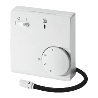
Uponor Comfort E Thermostat
dial Set T-85 230 V
Caution !
The device may only be opened and installed
according to the circuit diagram on the device or
these instructions by a qualified electrician. The
existing safety regulations must be observed.
Appropriate installation measures must be taken
to achieve the requirements of protection class II.
This independently mountable electronic device
is designed for controlling the temperature in
dry and enclosed rooms only under normal con
ditions. The device confirms to EN 60730, it works
according operating principle 1C.
1. Application
• Electric Floor Heating Systems
• Hot Water Floor Heating Systems
2. Operation
The controller recognizes the temperature via the
external remote sensor. The controller switches on
when sensor temperature is below set temperature
and it switches off as soon as required room tempera
ture (set value) will be reached and rise.
The setting range 1 ... 4 corresponds to temperature
10 ... 40 °C.
The controller can be switched ON and OFF by means
of the rocker switch.
Adjustable heating interrupt according standard EN
50559 (Interrupts heating after continous heating of
1hr for 5 Minutes).
2.1 Function of the lamps
Function
Lamp red
Heating is on
on
Floor sensor fault
flashes
2.2 Fault of the floor sensor
If a sensor fault (shortcircuit or break) occurs, the
controller will switch to fault mode. The heating will
function with max. 30 % of the energy (operation for
30 % of the time). This provides frost and overheat
protection.
3. Installation
a) Controller
– System to be wired free of voltage
– Pull off the adjusting knob
– Loosen the fixing screw
– Remove the cover
– Connection acc. to wiring diagram (inside cover)
b) Remote Sensor
Attention:
For more easy replacement sensor cable should
be put into a protection tube. The
can be lengthened up to 50 m by using a standard
2core cable for mains voltage and with a cross
section of 1,5 mm2. Close parallel routing along
high voltage cables or in cable ducts should be
avoided or otherwise a screened cable has to be
installed.
Attention:
In case of failure the sensor cable still can carry mains
voltage.
4. Wiring Diagram
5. Technical Data
Controller
Article no.
Switching current
Operating voltage at 50 Hz
Temperature range
depending on variant
Switch
Indicator lamp red
Control algorthm
Contact (Relay)
Switching differential
Protection class of housing
Degree of safety
Storage temperature
Pollution degree
Rated impulse voltage
Ball pressure test
temperature
Voltage and Current for
the purposes of
Interference measurements
Energy class
(acc. EU 811/2013, 812/2013, 813/2013, 814/2013)
Remote Sensor
Sensor identification
Sensing element
Sensor cable
Length of cable
Protection class
Ambient temperature
Characteristics of NTC resistor
Temperature range 10 ... 60°C
10 °C
20 °C
30 °C
40 °C
50 °C
60 °C
Ohmic values only can be tested on disconnected
sensor cable.
6. Dimensions
sensor cable
7. Limiting the temperature range
Preset of controller to max. setting range at factory.
Inside of adjustable knob there are 2 setting rings
with a range of 1 to 6. For limiting the range, please
consider following diagram.
T85 230 V
16 A (4 A cos ϕ = 0,6)
230 V AC (207 ... 253 V)
1 ... 4 (=10 ... 40 °C)
mains ON/OFF
Controller calls for heat
PID
1 n/o (for „heating")
approx. 1 K
IP 30
II (See point "Caution")
–20 ... +70 °C
2
4 kV
75 ± 2 °C
230 V, 0,1 A
IV = 2 %
white
NTC
PVC (2 x 0,5 mm2)
4 m, can be extended up
to 50m
IP 68
–25 ... +70 °C
*
[kΩ]
66,8
41,3
26,3
17,1
11,3
Uponor Corporation
7,5
Äyritie 20
01510 Vantaa
Finland
Range limitation
inside knob
6
5
4
3
2
1
10 16 22 28 34 40 °C
Setting range of controller
This product should not be disposed of with
household waste. Please recycle the products
where facilities for electronic waste exist. Check
with your local authorities for recycling advice.
T +358 (0)20 129 211
F +358 (0)20 129 2841
www.uponor.com
Advertisement

Related Manuals for Uponor T-85


Summary of Contents for Uponor T-85
- Page 1 – Loosen the fixing screw – Remove the cover Uponor Comfort E Thermostat – Connection acc. to wiring diagram (inside cover) dial Set T-85 230 V b) Remote Sensor Attention: For more easy replacement sensor cable should be put into a protection tube. The...
- Page 2 – Uvolněte upevňovací šroub – Sejměte kryt Uponor Comfort E Thermostat – Připojení podle schématu zapojení (vnitřní kryt) dial Set T-85 230V b) Dálkové čidlo Pozor: Pro snadnější výměnu kabelu čidla je vhodné umístit kabel do ochranné trubky. Kabel čidla lze prodloužit až...
- Page 3 – Abziehen des TemperaturEinstellknopfes Bedienungsanleitung – Lösen der Befestigungsschraube – Abnehmen des Gehäuseoberteils Uponor Comfort E Thermostat – Anschluß gemäß Schaltbild (siehe dial Set T-85 230 V Gehäuseoberteil) durchführen b) Temperaturfühler Achtung: Zum leichteren Austausch sollte der Temperaturfühler in einem Schutzrohr verlegt werden.
- Page 4 – Fjern låget Uponor Comfort E termostat – Tilslutning i henhold til ledningsdiagram (i låget) b) Fjernføler Dial T-85 230 V Bemærk: For nemmere udskiftning kan følerkablet placeres i en beskyttelsesslange. Følerkablet kan forlænges til op til 50 m ved hjælp af et standard 2-leder-kabel til netspænding og et tværsnit på...
- Page 5 – Retire la tapa – Conexión según el esquema de conexiones Uponor Comfort E Termostato (interior de la cubierta) con dial de ajuste T-85 230 V b) Sonda remota Atención: Para facilitar la sustitución, el cable de la sonda debe insertarse en un tubo de protección. El cable de la sonda se puede prolongar hasta los 50 ...
- Page 6 – Järjestelmän johdot kytketään jännitteettömänä Asennus- ja käyttöohjeet – Vedä säätimestä – Löysää kiinnitysruuvia Uponor Comfort E -termostaatin – Ota kansi pois näytön asetus T-85 230 V – Liitäntä kytkentäkaavion mukaisesti (kannen sisäpuolella) b) Etäanturi Huomio: Vaihdon helpottamiseksi anturin johto on asetettava suojaputkeen.
- Page 7 – Brancher selon le schéma Uponor Comfort E Thermostat (dans le couvercle du boîtier) b) Sonde de température dial Set T-85 230 V Attention: Pour faciliter un éventuel remplacement, placer la sonde dans un conduit de protection Le câble de sonde peut être prolongé jusqu’à...
- Page 8 – Húzza ki a beállítógombot – Lazítsa meg a rögzítőcsavart Uponor Comfort E Thermostat – Távolítsa el a burkolatot – Csatlakozás a kapcsolási rajz szerint dial Set T-85 230 V (a burkolat belső részén) b) Különálló hőmérséklet-érzékelő Figyelem! A csere megkönnyítése érdekében az érzékelő...
- Page 9 – Het schroefje onder de knop losdraaien. Uponor Comfort E Thermostat – De kap verwijderen. – Aansluiten volgens het schema (zie binnenzijde dial Set T-85 230 V kap). – Kap en instelknop wederom monteren. b) Temperatuurvoeler Let op!: Om uitwisseling in de toekomst mogelijk te maken dient u de voeler in een beschermbuis aan te brengen.
- Page 10 Installasjons- og bruksanvisning – Dra av justeringshjulet. Uponor Comfort E-termostat – Løsne festeskruen. – Ta av dekselet. med innstillingshjul T-85 230 V – Koble til i henhold til koblingsskjemaet (innsiden av dekselet). b) Ekstern føler Merk: For enklere utskifting bør følerkabelen legges i ...
-
Page 11: Instrukcja Montażu I Obsługi
– Ściągnąć pokrętło nastawcze temperatury – Poluzować śrubę mocującą Uponor Comfort E Thermostat – Zdjąć obudowę – Podłączenia elektryczne wykonać zgodnie ze sche- dial Set T-85 230V matem połączeń (patrz wewnątrz obudowy) b) Zdalny czujnik temperatury Uwaga: W celu zapewnienia łatwej wymiany czujnik tempera- tury należy osadzić... - Page 12 – Снять регулировочную ручку – Ослабить крепежные винты Uponor Comfort E Thermostat – Снять крышку – Выполнить подключение согласно схеме сое dial Set T-85 230 V динений (под крышкой) b) Выносной датчик температуры Внимание! Для упрощения последующей замены кабель датчика прокладывают в защитной трубке. Для...
- Page 13 – Ta bort locket Uponor Comfort E termostat – Anslutning enl. kopplingsschema (insidan av locket) b) Extern givare rattinställd T-85 230 V Obs! För enklare utbyte bör givarkabeln placeras i ett skyddsrör. Givarkabeln kan förlängas med upp till 50 m genom att en vanlig tvåledarkabel för nätström med en diameter på...
Need help?
Do you have a question about the T-85 and is the answer not in the manual?
Questions and answers