Advertisement
1812 Folder Disk Clutch Retrofit Kit
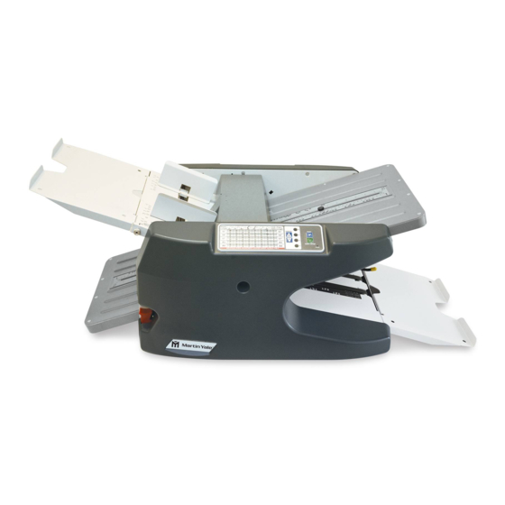
Background: Early production Martin Yale Model 1812 Folders were originally equipped with a
spring-clutch type feed wheel clutch. These units are identifiable by the presence of a keyed feed
wheel.
Current production 1812 folders (After S.N. 1812: 39568.01122.M38, 1812230: 39566.01001.MXX,
1812UK: 39566.01001.MXX) are equipped with a friction disk type feed wheel clutch in lieu of the
previous spring-clutch. Folders with the friction disk type clutch can be identified by the presence of
bearings in the bore of the feed wheel. They can also be identified by the fact that the feed wheel on
these folders will spin freely of the feed wheel shaft in the direction that paper feeds.
This retro-kit allows a technician to convert an older unit originally equipped with the spring-type
clutch to the current disk clutch.
Parts Included: The following parts are included with the WRA1812510 Clutch Retrofit Kit.
(1) M-S027951 Clutch Retro-Kit Instructions (this document)
(1) M-S001540 8-32 X 7/8 Truss Head Screw
(1) W-O2051368 Black Oxide Feed Wheel Shaft for Disk Clutch
(1) W-O2051369 Clutch Feed Wheel
(1) W-A2051085 Disk Type Feed Clutch Assembly
(1) M-S008126 #8 X .75" OD Fender Washer
(1) M-S010039 5133-18 E-Ring
(1) M-S045339 1812 Processor
(1) M-S019032 1/4 X 3/8 X .17ID Standoff
(1) M-S007006 8-32 Kep Nut
(2) M-S043021 .10 X 4 Blk Wire Tie
Tool List:
#2 Phillips Screwdriver-Medium Length
#2 Phillips Screwdriver-Short Length
Wire Cutters-Small to Medium Sized
11/32" Nut Driver, Socket/Ratchet/Extension, or Wrench
Flat Bladed Screwdriver-For Removal and Installation of E-Rings
Flat Bladed Screwdriver or Pen-Knife Blade-For Electronic Chip Removal on Logic Board
9/64" Hex Wrench
WARNING: Before any work is attempted on folder, assure that folder is disconnected
from power source by either removing the power cord or locking out the power source.
1) Remove (9) screws from the rear folder side cover (cover WITHOUT the operator panel in it) and
remove cover. This will expose the clutch mechanism See picture below for reference.
Installation Instructions
Martin Yale #WRA1812510
(1)
Advertisement
Table of Contents

Subscribe to Our Youtube Channel
Related Manuals for Martin Yale 1812


Summary of Contents for Martin Yale 1812
- Page 1 Installation Instructions 1812 Folder Disk Clutch Retrofit Kit Martin Yale #WRA1812510 Background: Early production Martin Yale Model 1812 Folders were originally equipped with a spring-clutch type feed wheel clutch. These units are identifiable by the presence of a keyed feed wheel.
- Page 2 Rear View of 1812 with Cover Removed 2) Locate existing spring-clutch using the picture below as a guide. Disconnect its electrical connec- tor and (2) mounting Kep Nuts using a 11/32” nut driver or socket. If the machine to clutch connector is wire-tied together, it may be necessary to cut that wire tie with a pair of wire cutters.
- Page 3 Installing New Feed Shaft into Folder---Note Orientation of Small Journal on End of Shaft. It Goes Towards the Side of Folder with Removed Sidecover!!!! 5) As Feed Shaft is inserted through sideframe, place a single plastic spacer (washer) on shaft. While holding the new Feed Wheel over retarder with the brass center bearing located towards the OPERATOR side of folder, push feed shaft through the Feed Wheel.
- Page 4 Grommet Stop Screw & Kep Nut Grommet Stop, Screw, and Standoff 8) Install electrical body of new clutch on feed shaft. It may be necessary to turn clutch upon installa- tion on the small end of the Feed Shaft to get their corresponding flats to align. There is a certain amount of ‘feel’...
- Page 5 Fender Washer and Small E-Ring Holding Clutch Gear in Position 11) Attach clutch electrical connector to machine harness. Orientation of the connectors to one an- other is not critical. A user-supplied plastic tie may be wrapped around connectors to assure they hold in position if desired.
- Page 6 ‘bypass’ on it and a bypass slot in the top cover, the board setting must be changed to ‘bypass’. Con- tact M-Y tech support at 800-225-5644 for instructions on how to change 1812 board settings. 16) Reset the paper retarder which is also called a sheet separator. It is directly below the feed...
- Page 7 Press the retarder (sheet separator) release button. This will release the pressure against the Feed Wheel and allow the technician to turn the Feed Wheel in the direction of paper feed. While the but- ton is depressed, the Feed Wheel should turn freely. Retarder pressure release button.
- Page 8 M-Y part #W- O2051369. See the parts list at the beginning of document for the M-Y numbers associated with the other parts replaced. 1812 with Disk Clutch Wiring Diagram 251 Wedcor Drive • Wabash, IN 46992 Phone (260)-563-0641 • Fax (260) 563-4575 Website: www.martinyale.com •...
Need help?
Do you have a question about the 1812 and is the answer not in the manual?
Questions and answers