WIKA TR10-A Operating Instructions Manual
Resistance thermometers (rtd) and thermocouples (tc)
Hide thumbs
Also See for TR10-A:
- Operating instructions manual (116 pages) ,
- Operating instructions manual (28 pages)
Table of Contents
Advertisement
Available languages
Available languages
Resistance thermometers (RTD) and thermocouples (TC)
Widerstandsthermometer (RTD) und Thermoelemente (TC)
Sondes à résistance (RTD) et thermocouples (TC)
Termorresistencias (RTD) y termopares (TC)
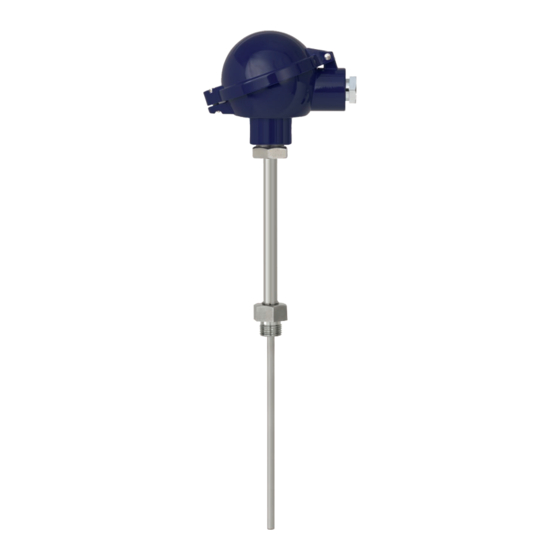
Examples/Beispiele/Exemples/Ejemplos
Operating instructions
Betriebsanleitung
Mode d'emploi
Manual de instrucciones
EN
DE
FR
ES
Advertisement
Chapters
Table of Contents

Related Manuals for WIKA TR10-A


Summary of Contents for WIKA TR10-A
- Page 1 Operating instructions Betriebsanleitung Mode d‘emploi Manual de instrucciones Resistance thermometers (RTD) and thermocouples (TC) Widerstandsthermometer (RTD) und Thermoelemente (TC) Sondes à résistance (RTD) et thermocouples (TC) Termorresistencias (RTD) y termopares (TC) Examples/Beispiele/Exemples/Ejemplos...
- Page 2 Page 47 - 68 Manual de instrucciones modelos RTD y TC Página 69 - 90 © 06/2010 WIKA Alexander Wiegand SE & Co. KG All rights reserved. / Alle Rechte vorbehalten. WIKA is a registered trademark in various countries. ®...
-
Page 3: Table Of Contents
3. Safety 4. Transport, packaging and storage 5. Commissioning, operation 6. Additional notes for instruments with EHEDG and 3-A 7. Faults 8. Maintenance, cleaning and calibration 9. Dismounting, return and disposal 10. Specifications 11. Accessories WIKA operating instructions RTD and TC... -
Page 4: General Information
The model TRxx or model TCxx thermometers consist of a welded tube, a mineral- insulated sheathed cable or ceramic-insulated thermocouple wires in which the temperature sensor is located. This is embedded in a ceramic powder, a temperature- resistant sealing compound, cement compound or a heat transfer paste. WIKA operating instructions RTD and TC... -
Page 5: Safety
... indicates a potentially dangerous situation that can result in light injuries or damage to equipment or the environment, if not avoided. WARNING! ... indicates a potentially dangerous situation that can result in burns, caused by hot surfaces or liquids, if not avoided. WIKA operating instructions RTD and TC... - Page 6 The system operator is responsible for selecting the thermometer or thermowell, and for the selection of their materials, so as to guarantee their safe operation within the plant or machine. When preparing a quote, WIKA can only give recommendations which are based on our experience in similar applications.
- Page 7 The personnel trained by the operator are understood to be personnel who, based on their education, knowledge and experience, are capable of carrying out the work described and independently recognising potential hazards. Special operating conditions require further appropriate knowledge, e.g. of aggressive media. WIKA operating instructions RTD and TC...
- Page 8 FT = Thin-film measuring resistor, sensitive tip ■ W = Wire-wound measuring resistor ■ Sensor in accordance with standard (thermocouple) ungrounded ■ grounded ■ Transmitter model (only for design with transmitter) Year of manufacture WIKA operating instructions RTD and TC...
-
Page 9: Transport, Packaging And Storage
Avoid exposure to the following factors: Direct sunlight or proximity to hot objects ■ Mechanical vibration, mechanical shock (putting it down hard) ■ Soot, vapour, dust and corrosive gases ■ Hazardous environments, flammable atmospheres ■ WIKA operating instructions RTD and TC... -
Page 10: Commissioning, Operation
As standard, WIKA uses copper seals for the connection between the neck tube and the thermowell, and a paper flat gasket for the connection of the connection head and the neck tube or thermowell. - Page 11 Repeated opening/closing is possible; however only if necessary, as it might have a ■ detrimental effect on the ingress protection For cable with a pronounced cold-flow behaviour the gland must be fully tightened. ■ WIKA operating instructions RTD and TC...
- Page 12 2 x Pt100, 2-wire 2 x Pt100, 3-wire 2 x Pt100, 4-wire black black yellow black yellow yellow white white white white white white white black black black black black yellow yellow yellow yellow 3160629.06 WIKA operating instructions RTD and TC...
- Page 13 4-wire white yellow white Lemosa connector Socket (female) Connector (male) Front view Front view 1 x Pt100 2-wire 1 x Pt100 3-wire 1 x Pt100 4-wire 2 x Pt100 2-wire 2 x Pt100 3-wire WIKA operating instructions RTD and TC...
- Page 14 Series 423 (shielded) Binder 1 x Pt100 Series 680 4-wire Series 423 (shielded) Binder 2 x Pt100 Series 680 2-wire Series 423 (shielded) Binder 2 x Pt100 Series 692 3-wire Amphenol 2 x Pt100 C16-3 4-wire WIKA operating instructions RTD and TC...
- Page 15 (screw-in plug) For the marking of the cable ends, see table Single thermocouple Dual thermocouple Thermo connector Positive and negative terminal are marked. Two thermo connectors are used with dual thermocouples. WIKA operating instructions RTD and TC...
- Page 16 For thermometers fitted with a connecting cable, the temperature at the interface with the connecting cable is restricted. The maximum is 150 °C. To ensure that the permissible temperature is not exceeded, the dimension X must be selected accordingly. WIKA operating instructions RTD and TC...
- Page 17 The length X is defined as the distance between the transition point from the cable to the heat-emitting surface. The expected temperature at the transition point should be a maximum of 120 °C. ▶ If necessary, the X length should be increased. Thread Thread (NPT) WIKA operating instructions RTD and TC...
-
Page 18: Additional Notes For Instruments With Ehedg And 3-A
Avoid thermal shocks or fast changes in the temperature. The temperature difference ■ between the cleaning agent and rinsing with clear water should be as low as possible. Negative example: Cleaning with 80 °C and rinsing at +4 °C with clear water. WIKA operating instructions RTD and TC... -
Page 19: Faults
Deposits on the sensor or Remove deposits thermowell WIKA operating instructions RTD and TC... -
Page 20: Maintenance, Cleaning And Calibration
Improper cleaning may lead to physical injuries and damage to property and the environment. Residual media in the dismounted instrument can result in a risk to persons, the environment and equipment. ▶ Carry out the cleaning process as described below. WIKA operating instructions RTD and TC... -
Page 21: Dismounting, Return And Disposal
Use the required protective equipment (depending on the application; the thermometer itself is basically not dangerous). ▶ Observe the information in the material safety data sheet for the corresponding medium. Only disconnect the thermometer once the system has been depressurised. WIKA operating instructions RTD and TC... - Page 22 Let the instrument cool down sufficiently before dismounting it! 9.2 Return Strictly observe the following when shipping the instrument: All instruments delivered to WIKA must be free from any kind of hazardous substances (acids, bases, solutions, etc.) and must therefore be cleaned before being returned. WARNING!
-
Page 23: Specifications
10. Specifications 10. Specifications Due to the large variance, the specifications are very extensive. Therefore we refer to the corresponding WIKA data sheets and also the order documentation. Thermocouples Resistance thermometers ■ ■ Model Data sheet Model Data sheet TC10-A TE 65.01... -
Page 24: Accessories
11. Accessories 11. Accessories The seals can be ordered from WIKA, indicating the WIKA order number and/ or the designation (see table). WIKA Designation Suitable for order number threads 11349981 per DIN 7603 form C 14 x 18 x 2 -CuFA G ¼, M14 x 1.5... - Page 25 3. Sicherheit 4. Transport, Verpackung und Lagerung 5. Inbetriebnahme, Betrieb 6. Zusätzliche Hinweise für Geräte mit EHEDG und 3-A 7. Störungen 8. Wartung, Reinigung und Kalibrierung 9. Demontage, Rücksendung und Entsorgung 10. Technische Daten 11. Zubehör WIKA Betriebsanleitung RTD und TC...
-
Page 26: Allgemeines
Das Thermometer Typ TRxx oder Typ TCxx besteht aus einem verschweißten Rohr, einer mineralisolierten Mantelleitung oder aus keramikisolierten Thermodrähten, worin sich der Temperatursensor befindet. Dieser ist in einem Keramikpulver, einer temperaturbeständi- gen Vergussmasse, Zementmasse oder einer Wärmeleitpaste eingebettet. WIKA Betriebsanleitung RTD und TC... -
Page 27: Sicherheit
Verletzungen bzw. Sach- und Umweltschäden führen kann, wenn sie nicht gemieden wird. WARNUNG! ... weist auf eine möglicherweise gefährliche Situation hin, die durch heiße Oberflächen oder Flüssigkeiten zu Verbrennungen führen kann, wenn sie nicht gemieden wird. WIKA Betriebsanleitung RTD und TC... - Page 28 Die Verantwortung für die Auswahl des Thermometers bzw. Schutzrohres, sowie für deren Werkstoffauswahl zur Gewährleistung einer sicheren Funktion in der Anlage bzw. Maschine obliegt dem Betreiber. WIKA kann während der Angebotserstellung lediglich Empfehlungen aussprechen, die sich an unseren Erfahrungen in ähnlichen Applikationen orientieren.
- Page 29 Das vom Betreiber geschulte Personal ist aufgrund seiner Bildung, Kenntnisse und Erfahrungen in der Lage, die beschriebenen Arbeiten auszuführen und mögliche Gefahren selbstständig zu erkennen. Spezielle Einsatzbedingungen verlangen weiteres entsprechendes Wissen, z. B. über aggressive Medien. WIKA Betriebsanleitung RTD und TC...
- Page 30 Angaben zur Ausführung (Messelement, Messbereich...) Sensor gemäß Norm (Widerstandsthermometer) Dünnfilm-Messwiderstand ■ FT = Dünnfilm-Messwiderstand, spitzensensitiv ■ W = Drahtgewickelter Messwiderstand ■ Sensor gemäß Norm (Thermoelement) ungrounded ■ grounded ■ Transmittertyp (nur bei Ausführung mit Transmitter) Herstellungsjahr WIKA Betriebsanleitung RTD und TC...
-
Page 31: Transport, Verpackung Und Lagerung
Betriebsanleitung des entsprechenden Transmitters Folgende Einflüsse vermeiden: Direktes Sonnenlicht oder Nähe zu heißen Gegenständen ■ Mechanische Vibration, mechanischer Schock (hartes Aufstellen) ■ Ruß, Dampf, Staub und korrosive Gase ■ Explosionsgefährdete Umgebung, entzündliche Atmosphären ■ WIKA Betriebsanleitung RTD und TC... -
Page 32: Inbetriebnahme, Betrieb
Gewinden (z. B. G ½, M20 x 1,5 ...) verbunden werden, müssen diese Gewinde mit Dichtungen gegen den Eintritt von Flüssigkeiten in das Thermometer gesichert werden. WIKA verwendet standardmäßig eine Kupferdichtung für die Verbindung Halsrohr zum Schutzrohr und eine Papier-Flachdichtung für die Verbindung Anschlusskopf zum Halsrohr oder Schutzrohr. - Page 33 Bei Verwendung sehr weicher Kabeltypen nicht den unteren Klemmbereich verwenden. ■ Nur Rundkabel verwenden (ggf. leicht ovaler Querschnitt). ■ Kabel nicht verdrillen. ■ Mehrmaliges Öffnen/Schließen möglich; hat ggf. jedoch negative Auswirkung auf die ■ Schutzart Bei Kabeln mit ausgeprägtem Kaltfließverhalten Verschraubung nachziehen. ■ WIKA Betriebsanleitung RTD und TC...
- Page 34 2 x Pt100, 2-Leiter 2 x Pt100, 3-Leiter 2 x Pt100, 4-Leiter schwarz schwarz gelb gelb schwarz gelb weiß weiß weiß weiß weiß weiß weiß schwarz schwarz schwarz schwarz schwarz gelb gelb gelb gelb 3160629.06 WIKA Betriebsanleitung RTD und TC...
- Page 35 4-Leiter weiß gelb weiß Lemosa-Stecker Kupplung (female) Stecker (male) Ansicht von vorn Ansicht von vorn 1 x Pt100 2-Leiter 1 x Pt100 3-Leiter 1 x Pt100 4-Leiter 2 x Pt100 2-Leiter 2 x Pt100 3-Leiter WIKA Betriebsanleitung RTD und TC...
- Page 36 Serie 423 (geschirmt) Binder 1 x Pt100 Serie 680 4-Leiter Serie 423 (geschirmt) Binder 2 x Pt100 Serie 680 2-Leiter Serie 423 (geschirmt) Binder 2 x Pt100 Serie 692 3-Leiter Amphenol 2 x Pt100 C16-3 4-Leiter WIKA Betriebsanleitung RTD und TC...
- Page 37 Mit Kabel oder Stecker ■ Lemosa-Stecker, Binder-Stecker, Kabel male am Kabel male am Kabel (Schraub-Steck-Verbindung) Kennzeichnung der Adernenden siehe Tabelle Einfach- Thermopaar Doppel- Thermopaar Thermostecker Plus-Pol und Minus-Pol sind gekennzeichnet. Bei doppelten Thermopaaren werden zwei Thermostecker verwendet. WIKA Betriebsanleitung RTD und TC...
- Page 38 100 mm Bei Thermometern mit Anschlussleitung wird die Temperatur an der Übergangsstelle zum Anschlusskabel eingeschränkt. Diese beträgt max. 150 °C. Durch Auswahl des Maßes X kann sichergestellt werden dass die zulässige Temperatur nicht überschritten wird. WIKA Betriebsanleitung RTD und TC...
- Page 39 Die Länge X ist als Abstand zwischen der Übergangsstelle auf dem Kabel zur wärmestrah- lenden Oberfläche definiert. Die zu erwartende Temperatur an der Übergangsstelle beträgt dabei maximal 120 °C. ▶ Gegebenenfalls die X-Länge entsprechend erhöhen. Gewinde Gewinde (NPT) WIKA Betriebsanleitung RTD und TC...
-
Page 40: Zusätzliche Hinweise Für Geräte Mit Ehedg Und 3-A
■ Teile korrosiv angreifen. Temperaturschocks oder schnelle Temperaturänderungen vermeiden. Die Temperatur- ■ differenz zwischen Reinigungsmittel und Klarspülung mit Wasser sollte möglichst gering sein. Negativbeispiel: Reinigung mit 80 °C und Klarspülung mit +4 °C kaltem Wasser. WIKA Betriebsanleitung RTD und TC... -
Page 41: Störungen
Der temperaturempfindliche Bereich Messwerte und zu zu geringe Einbautiefe oder zu des Sensors muss innerhalb des hohe Wärmeableitung Mediums liegen, Oberflächen- lange Ansprechzeiten messungen müssen isoliert sein Ablagerungen auf dem Sensor Ablagerungen entfernen oder Schutzrohr WIKA Betriebsanleitung RTD und TC... -
Page 42: Wartung, Reinigung Und Kalibrierung
8.2 Reinigung VORSICHT! Körperverletzungen, Sach- und Umweltschäden Eine unsachgemäße Reinigung führt zu Körperverletzungen, Sach- und Umweltschäden. Messstoffreste im ausgebauten Gerät können zur Gefähr- dung von Personen, Umwelt und Einrichtung führen. ▶ Reinigungsvorgang wie folgt beschrieben durchführen. WIKA Betriebsanleitung RTD und TC... -
Page 43: Demontage, Rücksendung Und Entsorgung
Personen und Umwelt vor Gefährdung durch anhaftende Messstoffreste zu schützen. ▶ Notwendige Schutzausrüstung verwenden (abhängig von der jeweiligen Applikation; Das Thermometer selbst ist prinzipiell ungefährlich.). ▶ Angaben im Sicherheitsdatenblatt für den entsprechenden Messstoff beachten. Thermometer nur im drucklosen Zustand demontieren. WIKA Betriebsanleitung RTD und TC... - Page 44 Vor dem Ausbau das Gerät ausreichend abkühlen lassen! 9.2 Rücksendung Beim Versand des Gerätes unbedingt beachten: Alle an WIKA gelieferten Geräte müssen frei von Gefahrstoffen (Säuren, Laugen, Lösun- gen, etc.) sein und sind daher vor der Rücksendung zu reinigen. WARNUNG! Körperverletzungen, Sach- und Umweltschäden durch Messstoffreste...
-
Page 45: Technische Daten
10. Technische Daten 10. Technische Daten Aufgrund der hohen Varianz sind die technischen Daten sehr umfangreich. Daher verwei- sen wir auf die entsprechenden WIKA-Datenblätter sowie die Bestellunterlagen. Widerstandsthermometer Thermoelemente ■ ■ Datenblatt Datenblatt TR10-A TE 60.01 TC10-A TE 65.01 TR10-B TE 60.02... -
Page 46: Zubehör
11. Zubehör 11. Zubehör Dichtungen können unter Angabe der Gewinde mit WIKA-Bestellnummer und/oder Bezeichnung (siehe Tabelle) bei WIKA bezogen werden. WIKA Bezeichnung Geeignet für Bestellnummer Gewinde 11349981 nach DIN 7603 Form C 14 x 18 x 2 -CuFA G ¼, M14 x 1,5... - Page 47 4. Transport, emballage et stockage 5. Mise en service, utilisation 6. Notes supplémentaires pour instruments avec EHEDG et 3-A 62 7. Dysfonctionnements 8. Entretien, nettoyage et etalonnage 9. Démontage, retour et mise au rebut 10. Spécifications 11. Accessoires WIKA mode d‘emploi RTD et TC...
-
Page 48: Conception Et Fonction
Sous réserve de modifications techniques. ■ Pour obtenir d'autres informations : ■ - Consulter notre site Internet : www.wika.fr Tel.: 0 820 951010 - Conseiller applications : (0,15 €/min) +33 1 787049-46 Fax: 0 891 035891 (0,35 €/min) -
Page 49: Sécurité
évitée. AVERTISSEMENT ! … indique une situation présentant des risques susceptibles de provoquer des brûlures dues à des surfaces ou liquides chauds si elle n'est pas évitée. WIKA mode d‘emploi RTD et TC... - Page 50 L'opérateur du système est responsable du choix du thermomètre ou du doigt de gant, et aussi du choix de leurs matériaux pour garantir leur fonctionnement en toute sécurité sur l'installation ou la machine. En soumettant une offre, WIKA peut seulement donner des recommandations fondées sur notre expérience dans des applications similaires.
- Page 51 Le personnel formé par l'opérateur est, en raison de sa formation et de son expérience en mesure d'effectuer les travaux décrits et de reconnaître de façon autonome les dangers potentiels. Les conditions d'utilisation spéciales exigent également une connaissance adéquate par exemple des liquides agressifs. WIKA mode d‘emploi RTD et TC...
- Page 52 W = Résistance de mesure bobinée ■ Capteur conforme à la norme Point de mesure isolé ■ Point de mesure non isolé ■ Type de transmetteur (uniquement pour version avec transmetteur) Année de fabrication WIKA mode d‘emploi RTD et TC...
-
Page 53: Transport, Emballage Et Stockage
Eviter les influences suivantes : Lumière solaire directe ou proximité d'objets chauds ■ Vibrations mécaniques, chocs mécaniques (mouvements brusques en le posant) ■ Suie, vapeur, poussière et gaz corrosifs ■ Environnements dangereux, atmosphères inflammables ■ WIKA mode d‘emploi RTD et TC... -
Page 54: Mise En Service, Utilisation
être protégés à l'aide de joints qui empêchent la pénétration de liquides dans le thermomètre. Comme standard, WIKA utilise des joints d'étanchéité en cuivre pour la connexion entre l'extension et le doigt de gant, et un joint d'étanchéité plat en papier pour la connexion de la tête de raccordement et de l'extension ou le doigt de gant. - Page 55 Une ouverture/fermeture répétée est possible ; mais toutefois seulement si c'est ■ nécessaire, car cela pourrait se produire au détriment de l'indice de protection. Pour un câble avec un comportement de flux froid prononcé, le presse-étoupe doit être ■ bien serré. WIKA mode d‘emploi RTD et TC...
- Page 56 2 x Pt100, 4 fils noir noir jaune rouge jaune noir jaune blanc blanc blanc rouge rouge rouge rouge rouge rouge rouge blanc blanc blanc blanc noir noir noir noir noir jaune jaune jaune jaune 3160629.06 WIKA mode d‘emploi RTD et TC...
- Page 57 Prise (femelle) Connecteur (mâle) Vue de face Vue de face 1 x Pt100 2 fils 1 x Pt100 3 fils 1 x Pt100 4 fils 2 x Pt100 2 fils 2 x Pt100 3 fils WIKA mode d‘emploi RTD et TC...
- Page 58 1 x Pt100 Série 423 (blindé) 4 fils Binder Série 680 2 x Pt100 Série 423 (blindé) 2 fils Binder 2 x Pt100 Série 692 3 fils 2 x Pt100 Amphenol 4 fils C16-3 WIKA mode d‘emploi RTD et TC...
- Page 59 (connecteur à visser) Pour le marquage des extrémités de câbles, voir tableau Thermocouple unique Thermocouple double Connecteur Les bornes positives et négatives sont marquées. thermocouple Deux connecteurs thermocouple sont utilisés avec des double thermocouples. WIKA mode d‘emploi RTD et TC...
- Page 60 Pour les thermomètres équipés d'un câble de connexion, la température à l'interface avec le câble de connexion est limitée. Le maximum est de 150 °C. Pour assurer que la température admissible ne soit pas dépassée, la dimension X doit être choisie en conséquence. WIKA mode d‘emploi RTD et TC...
- Page 61 La longueur X est définie comme étant la distance entre le point de transition depuis le câble et la surface émettant de la chaleur. La température attendue au point de transition ne doit pas dépasser 120 °C. ▶ Si nécessaire, il faudra augmenter la longueur X. Filetage Filetage (NPT) WIKA mode d‘emploi RTD et TC...
-
Page 62: Notes Supplémentaires Pour Instruments Avec Ehedg Et 3-A
■ de température entre l‘agent de nettoyage et le rinçage à l‘eau claire doit être aussi faible que possible. Exemple négatif : nettoyage à 80 °C et rinçage à +4 °C à l‘eau claire. WIKA mode d‘emploi RTD et TC... -
Page 63: Dysfonctionnements
Utiliser un doigt de gant adéquat. attaque chimique Valeurs mesurées Pénétration d'humidité dans le Remplacer le capteur ou l'insert erronées (trop câble ou l'élément de mesure de mesure par un autre ayant une conception adaptée basses) WIKA mode d‘emploi RTD et TC... -
Page 64: Entretien, Nettoyage Et Etalonnage
équipements ou à l'environnement. Les restes de fluides se trouvant dans les instruments démontés peuvent mettre en danger les personnes, l'environnement ainsi que l'installation. ▶ Effectuer la procédure de nettoyage comme décrit ci-dessous. WIKA mode d‘emploi RTD et TC... -
Page 65: Démontage, Retour Et Mise Au Rebut
▶ Observer les informations de la fiche technique de sécurité de matériau pour le fluide correspondant. Déconnecter le thermomètre seulement si le système a été mis hors pression ! WIKA mode d‘emploi RTD et TC... - Page 66 ! 9.2 Retour En cas d'envoi de l'instrument, il faut respecter impérativement ceci : Tous les instruments livrés à WIKA doivent être exempts de substances dangereuses (acides, bases, solutions, etc.) et doivent donc être nettoyés avant d'être retournés. AVERTISSEMENT ! Blessures physiques et dommages aux équipements et à...
-
Page 67: Spécifications
10. Spécifications 10. Spécifications En raison du grand nombre de variantes, les spécifications sont très étendues. C'est pourquoi nous renvoyons à la fiche technique WIKA correspondante et aussi à la documentation de commande. Sondes à résistance Thermocouples ■ ■ Type... -
Page 68: Accessoires
11. Accessoires 11. Accessoires Les joints peuvent être commandés auprès de WIKA, en indiquant le code article WIKA et/ou la désignation (voir tableau). WIKA Désignation Convient aux N° de commande filetages 11349981 selon DIN 7603 forme C 14 x 18 x 2 -CuFA G ¼, M14 x 1,5... - Page 69 5. Puesta en servicio, funcionamiento 6. Indicaciones adicionales para instrumentos con EHEDG y 3-A 7. Errores 8. Mantenimiento, limpieza y calibración 9. Desmontaje, devolución y eliminación de residuos 10. Datos técnicos 11. Accesorios WIKA manual de instrucciones RTD y TC...
-
Page 70: Información General
Éste está compactado en un polvo de cerámica, una masa de relleno resistente a la temperatura, una masa de cemento o una pasta térmica. WIKA manual de instrucciones RTD y TC... -
Page 71: Seguridad Es
¡ADVERTENCIA! ... indica una situación probablemente peligrosa que puede causar quemaduras debido a superficies o líquidos calientes si no se evita. WIKA manual de instrucciones RTD y TC... - Page 72 La responsabilidad de selección del termómetro y la vaina así como la selección del material para asegurar el funcionamiento seguro de la instalación o de la máquina asume la empresa propietaria/operadora. Durante la elaboración de la oferta, WIKA puede dar recomendaciones únicamente basadas en experiencias con aplicaciones similares.
- Page 73 El personal formado por el usuario es capaz de realizar el trabajo descrito y de identificar los peligros potenciales debido a su formación, el conocimiento y la experiencia. Algunas condiciones de uso específicas requieren conocimientos adicionales, p. ej. acerca de medios agresivos. WIKA manual de instrucciones RTD y TC...
- Page 74 W = Resistor bobinado ■ Sensor conforme a norma Sin conexión a tierra ■ Con conexión a tierra ■ Modelo de transmisor (sólo en la variante con transmisor) Año de fabricación WIKA manual de instrucciones RTD y TC...
-
Page 75: Transporte, Embalaje Y Almacenamiento
Evitar lo siguiente: Luz solar directa o proximidad a objetos calientes ■ Vibración mecánica, impacto mecánico (colocación brusca) ■ Hollín, vapor, polvo y gases corrosivos ■ Entorno potencialmente explosivo, atmósferas inflamables ■ WIKA manual de instrucciones RTD y TC... -
Page 76: Puesta En Servicio, Funcionamiento
(si se han pedido). El propietario de la instalación debe controlar la idoneidad de las juntas para las condiciones de uso y debe sustituirlas por juntas adecuadas si fuera necesario (véase el capítulo 11 „Accesorios“). ¡Sustituir las juntas tras finalizar el desmontaje! WIKA manual de instrucciones RTD y TC... - Page 77 Es posible abrir y cerrar repetidamente; sin embargo puede afectar el grado de ■ protección En cables de elevada susceptibilidad a efectos causados por flujo en frío se debe ■ reapretar el racordaje. WIKA manual de instrucciones RTD y TC...
- Page 78 2 x Pt100, 4 hilos negro negro amarillo negro rojo amarillo blanco amarillo blanco blanco rojo rojo rojo rojo rojo rojo rojo blanco blanco blanco blanco negro negro negro negro negro amarillo amarillo amarillo amarillo 3160629.06 WIKA manual de instrucciones RTD y TC...
- Page 79 Conexión (hembrilla) Clavija (macho) Vista frontal Vista frontal 1 x Pt100 2 hilos 1 x Pt100 3 hilos 1 x Pt100 4 hilos 2 x Pt100 2 hilos 2 x Pt100 3 hilos WIKA manual de instrucciones RTD y TC...
- Page 80 Serie 680 4 hilos Serie 423 (blindado) Binder 2 x Pt100 Serie 680 2 hilos Serie 423 (blindado) Binder 2 x Pt100 Serie 692 3 hilos Amphenol 2 x Pt100 C16-3 4 hilos WIKA manual de instrucciones RTD y TC...
- Page 81 Para identificación de los extremos de conductores, veáse la tabla Termopar simple Termopar doble Conector térmico El polo positivo y el polo negativo están identificados. En los termopares dobles se emplean dos termoconectores. WIKA manual de instrucciones RTD y TC...
- Page 82 En termómetros con cable de conexión, la temperatura en el punto de transición al cable de conexión es limitada. Ésta es de máx. 150 °C. Seleccionando la medida X puede asegurarse que no se supere la temperatura permitida. WIKA manual de instrucciones RTD y TC...
- Page 83 La longitud X está definida como la distancia entre el punto de transición en el cable y la superficie de radiación térmica. La temperatura previsible en el punto de transición es de 120 °C como máximo. ▶ Si fuera necesario, aumentar la longitud X de manera correspondiente. Rosca(NPT) Rosca WIKA manual de instrucciones RTD y TC...
-
Page 84: Indicaciones Adicionales Para Instrumentos Con Ehedg Y 3-A
Evite choques de temperatura o cambios rápidos de temperatura. La diferencia de ■ temperatura entre el detergente y el enjuague con agua debe ser lo más baja posible. Ejemplo negativo: limpieza con 80 °C y enjuague con +4 °C de agua fría. WIKA manual de instrucciones RTD y TC... -
Page 85: Errores
Depósitos en el sensor o la vaina Eliminar los residuos WIKA manual de instrucciones RTD y TC... -
Page 86: Mantenimiento, Limpieza Y Calibración
Una limpieza inadecuada provoca lesiones corporales, daños materiales y del medio ambiente. Medios residuales en el instrumento desmontado pueden causar riesgos para personas, medio ambiente e instalación. ▶ Realizar el proceso de limpieza tal como se describe a continuación. WIKA manual de instrucciones RTD y TC... -
Page 87: Desmontaje, Devolución Y Eliminación De Residuos
Utilizar el equipo de protección necesario (en función de la aplicación correspondiente; El termómetro mismo en principio no es peligroso.). ▶ Observar la ficha de datos de seguridad correspondiente al medio. Desmontar la sonda solo en estado despresurizado. WIKA manual de instrucciones RTD y TC... - Page 88 ¡Dejar enfriar el instrumento lo suficiente antes de desmontarlo! 9.2 Devolución Es imprescindible observar lo siguiente para el envío del instrumento: Todos los instrumentos enviados a WIKA deben estar libres de sustancias peligrosas (ácidos, lejías, soluciones, etc.) y, por lo tanto, deben limpiarse antes de devolver. ¡ADVERTENCIA! Lesiones corporales, daños materiales y del medio ambiente por...
-
Page 89: Datos Técnicos
10. Datos técnicos 10. Datos técnicos Debido a la gran variedad hay amplios datos técnicos. Por esto remitimos a las hojas técnicas de WIKA y a la documentación de pedida. Termorresistencias Termopares ■ ■ Modelo Hoja técnica Modelo Hoja técnica TR10-A TE 60.01... -
Page 90: Accesorios
11. Accesorios 11. Accesorios Las juntas pueden pedirse a WIKA indicando el número de pedido y/o la referencia (véase la tabla). WIKA Denominación Adecuado para N° de pedido roscas 11349981 según DIN 7603 forma C 14 x 18 x 2 -CuFA G ¼, M14 x 1,5... - Page 91 WIKA operating instructions RTD and TC...
- Page 92 WIKA subsidiaries worldwide can be found online at www.wika.com. WIKA-Niederlassungen weltweit finden Sie online unter www.wika.de. La liste des filiales WIKA dans le monde se trouve sur www.wika.fr. Sucursales WIKA en todo el mundo puede encontrar en www.wika.es. WIKA Alexander Wiegand SE & Co. KG Alexander-Wiegand-Strasse 30 63911 Klingenberg •...
Need help?
Do you have a question about the TR10-A and is the answer not in the manual?
Questions and answers