WIKA TR25 Operating Instructions Manual
In-line resistance thermometer
intrinsically safe designs (ex i)
Hide thumbs
Also See for TR25:
- Operating instructions manual (92 pages) ,
- Operating instructions manual (116 pages) ,
- Operating instructions manual (28 pages)
Table of Contents
Advertisement
Available languages
Available languages
Quick Links
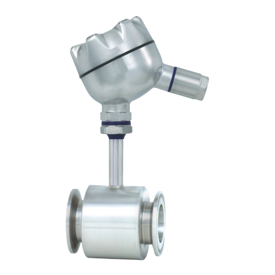
In-line resistance thermometer, model TR25
Intrinsically safe designs (Ex i)
Rohr-In-Line-Widerstandsthermometer, Typ TR25
Eigensichere Ausführungen (Ex i)
In-line resistance thermometer, Ex i, model TR25
Options: Sealing combination at neck tube, cable gland in hygienic design
®
TYPE EL
CLASS I
JUNE 2018
Operating instructions
Betriebsanleitung
EN
DE
Advertisement
Chapters
Table of Contents

Related Manuals for WIKA TR25


Summary of Contents for WIKA TR25
- Page 1 In-line resistance thermometer, model TR25 Intrinsically safe designs (Ex i) Rohr-In-Line-Widerstandsthermometer, Typ TR25 Eigensichere Ausführungen (Ex i) ® TYPE EL CLASS I JUNE 2018 In-line resistance thermometer, Ex i, model TR25 Options: Sealing combination at neck tube, cable gland in hygienic design...
- Page 2 Betriebsanleitung Typ TR25 (Ex i) Seite 33 - 62 Further languages can be found at www.wika.com. © 10/2013 WIKA Alexander Wiegand SE & Co. KG All rights reserved. / Alle Rechte vorbehalten. ® WIKA is a registered trademark in various countries.
-
Page 3: Table Of Contents
10. Calculation examples for self-heating of the tubular body at the sensor installation point 11. Maintenance and cleaning 12. Faults 13. Dismounting, return and disposal Appendix: EU declaration of conformity Declarations of conformity can be found online at www.wika.com. WIKA operating instructions model TR25 (Ex i) -
Page 4: General Information
... indicates a potentially dangerous situation that can result in light injuries or damage to equipment or the environment, if not avoided. Information ... points out useful tips, recommendations and information for efficient and trouble-free operation. WIKA operating instructions model TR25 (Ex i) -
Page 5: Safety
The technical specifications contained in these operating instructions must be observed. Improper handling or operation of the instrument outside of its technical specifications requires the instrument to be taken out of service immediately and inspected by an authorised WIKA service engineer. WIKA operating instructions model TR25 (Ex i) - Page 6 (pressure rating) as the vessel or pipeline. The thermowells and the measuring instruments are not suitable for abrasive ■ media. WIKA operating instructions model TR25 (Ex i)
- Page 7 ■ work safety, first aid and environmental protection and know the operating instructions and, in particular, the safety instructions contained therein. WIKA operating instructions model TR25 (Ex i)
- Page 8 Should a failure occur, aggressive media with extremely high temperature and under high pressure or vacuum may be present at the instrument. DANGER! Make sure that the thermowell is sufficiently earthed. WIKA operating instructions model TR25 (Ex i)
- Page 9 Information on version (measuring element, output signal, measuring range...) Sensor in accordance with standard: F (Thin-film resistor) Approval-related data Before mounting and commissioning the instrument, ensure you read the operating instructions! WIKA operating instructions model TR25 (Ex i)
-
Page 10: Specifications
WIKA confirms conformity with the Pressure Equipment Directive in accordance with the conformity assessment procedure, module H. For further specifications see WIKA data sheet TE 60.25 and the order documentation. WIKA operating instructions model TR25 (Ex i) -
Page 11: Design And Function
Version with clamp connection ■ Connection head Terminal block, transmitter (option) Tubular body Legend: Neck tube length N (M ) Neck length Insertion length Ø D Inner diameter of pipe Ø D Clamp fitting WIKA operating instructions model TR25 (Ex i) - Page 12 2) Maximum operating temperature 150 °C 3) All thermowells of this series that are internally pressurised, with a nominal diameter (DN) > 25 mm, are manufactured and tested to module H of the pressure equipment directive. WIKA operating instructions model TR25 (Ex i)
-
Page 13: Thread Neumo Bioconnect
Rd 65 x 1/6 84 70 40 53 x 1.5 Rd 78 x 1/6 84 70 25 Flange connections, clamp connections and further 70 x 2 Rd 95 x 1/6 88 72 25 nominal widths on request. WIKA operating instructions model TR25 (Ex i) -
Page 14: Transport, Packaging And Storage
WARNING! Before storing the instrument (following operation), remove any residual media. This is of particular importance if the medium is hazardous to health, e.g. caustic, toxic, carcinogenic, radioactive, etc. WIKA operating instructions model TR25 (Ex i) -
Page 15: Commissioning, Operation
In addition this expert must provide a certificate for this and provide the equipment with a test mark. WIKA operating instructions model TR25 (Ex i) - Page 16 When using a thermowell/neck tube, the overall instrument must be designed such that it allows installation in a way that results in a sufficiently tight gap (IP67) or a flameproof gap (IEC/EN 60079-1) towards the less hazardous area. WIKA operating instructions model TR25 (Ex i)
- Page 17 Moreover, they feature housings made of stainless steel and cable glands for low-temperature ranges When there is a built-in transmitter and/or a digital display, the special conditions from the type examination certificate (see item 17) apply. WIKA operating instructions model TR25 (Ex i)
- Page 18 Where there are neither transmitters nor digital displays mounted within the housing, there will also be no additional warming. With a built-in transmitter (optionally with digital display), heating caused by the operation of the transmitter or digital display may occur. WIKA operating instructions model TR25 (Ex i)
- Page 19 (e.g. T2) than the marked one is permissible. In doing so, it must be ensured that the maximum ambient temperature for safe operation of the instrument is not exceeded. WIKA operating instructions model TR25 (Ex i)
- Page 20 50 mm 50 mm > 200 °C ≤ 450 °C 100 mm 100 mm WARNING! For reasons of work safety and saving of resources, hot surfaces should be protected against accidental touch and energy loss by means of insulation. WIKA operating instructions model TR25 (Ex i)
- Page 21 The sensor together with housing or connection head is located in Zone 0 (Zone 20). An Ex ia type circuit must be used. Connection heads/cases made of aluminium are not permitted in zone 0. At this position, WIKA uses connection heads/cases made of stainless steel.
- Page 22 The welded parts, process connections, compression fittings, thermowells or housings used must be designed such that they withstand all influencing variables resulting from the process, such as temperature, flow forces, pressure, corrosion, vibration and impacts. WIKA operating instructions model TR25 (Ex i)
-
Page 23: Additional Notes For Instruments With Ehedg And 3-A
Avoid thermal shocks or fast changes in the temperature. The temperature difference ■ between the cleaning agent and rinsing with clear water should be as low as possible. Negative example: Cleaning with 80 °C and rinsing at +4 °C with clear water. WIKA operating instructions model TR25 (Ex i) -
Page 24: Electrical Connection Values
3) Use in methane atmospheres Owing to the higher minimum ignition energy of methane, the instruments can also be used where methane causes a potentially explosive atmosphere. The instrument can be optionally marked with IIC + WIKA operating instructions model TR25 (Ex i) - Page 25 The transmitters/digital displays used for the application range in accordance with the FISCO model are considered FISCO field units. The requirements in accordance with IEC/EN 60079-27, and the connection conditions of the approvals in accordance with FISCO, apply. WIKA operating instructions model TR25 (Ex i)
-
Page 26: Calculation Examples For Self-Heating Of The Tubular Body At The Sensor Installation Point
9. Calculation examples for self-heating of the tubular ... 10. Calculation examples for self-heating of the tubular body at the sensor installation point In-line resistance thermometer model TR25 with built-in head-mounted transmitter model T32.1S. Power supply is, for example, via a model KFD2-STC4-EX1 transducer power supply (WIKA Article No. -
Page 27: Maintenance And Cleaning
It is recommended that the measuring instrument is recalibrated at regular intervals of approx. 24 months. This period can reduce, depending on the particular application. The measuring instrument must be dismounted for calibration. The calibration can only be carried out by the manufacturer. WIKA operating instructions model TR25 (Ex i) -
Page 28: Faults
In this case, contact the manufacturer. If a return is needed, follow the instructions given in chapter 13.2 “Return”. WIKA operating instructions model TR25 (Ex i) -
Page 29: Dismounting, Return And Disposal
WARNING! Strictly observe the following when shipping the instrument: All instruments delivered to WIKA must be free from any kind of hazardous substances (acids, bases, solutions, etc.). When returning the instrument, use the original packaging or a suitable transport package. -
Page 30: Appendix: Eu Declaration Of Conformity
Appendix: EU declaration of conformity WIKA operating instructions model TR25 (Ex i) - Page 31 Appendix: EU declaration of conformity WIKA operating instructions model TR25 (Ex i)
- Page 32 Appendix: EU declaration of conformity WIKA operating instructions model TR25 (Ex i)
- Page 33 8. Zusätzliche Hinweise für Geräte mit EHEDG und 3-A 9. Elektrische Anschlusswerte 10. Berechnungsbeispiele für die Eigenerwärmung des Rohrkörpers an der Sensoreinbaustelle 11. Wartung und Reinigung 12. Störungen 13. Demontage, Rücksendung und Entsorgung Anlage: EU-Konformitätserklärung Konformitätserklärungen finden Sie online unter www.wika.de. WIKA Betriebsanleitung Typ TR25 (Ex i)
-
Page 34: Allgemeines De
… weist auf eine möglicherweise gefährliche Situation hin, die zu geringfügigen oder leichten Verletzungen bzw. Sach- und Umweltschäden führen kann, wenn sie nicht gemieden wird. Information … hebt nützliche Tipps und Empfehlungen sowie Informationen für einen effizi- enten und störungsfreien Betrieb hervor. WIKA Betriebsanleitung Typ TR25 (Ex i) -
Page 35: Sicherheit
Die technischen Spezifikationen in dieser Betriebsanleitung sind einzuhalten. Eine unsachgemäße Handhabung oder ein Betreiben des Gerätes außerhalb der technischen Spezifikationen macht die sofortige Stilllegung und Überprüfung durch einen autorisierten WIKA-Servicemitarbeiter erforderlich. WIKA Betriebsanleitung Typ TR25 (Ex i) - Page 36 Festigkeit (Druckstufe) wie der Behälter oder die Rohrleitung aufweisen. Die Schutzrohre bzw. Messgeräte sind nicht für abrasiven Medien geeignet. ■ Den Ein-/Ausbau nur im drucklosen Zustand vornehmen. Vorsicht vor heißen ■ Oberflächen und Restmedien! WIKA Betriebsanleitung Typ TR25 (Ex i)
- Page 37 ■ Bedarf jederzeit Hilfe zur Stelle ist. dass das Bedienpersonal regelmäßig in allen zutreffenden Fragen von ■ Arbeitssicherheit, Erste-Hilfe und Umweltschutz unterwiesen wird, sowie die Betriebsanleitung und insbesondere die darin enthaltenen Sicherheitshinwei- se kennt. WIKA Betriebsanleitung Typ TR25 (Ex i)
- Page 38 Dieses Gerät nicht in Sicherheits- oder in Not-Aus-Einrichtungen benutzen. Fehlerhafte Anwendungen des Gerätes können zu Verletzungen führen. Am Gerät können im Fehlerfall aggressive Medien mit extremer Temperatur und unter hohem Druck oder Vakuum anliegen. GEFAHR! Auf ausreichende Erdung des Schutzrohres achten. WIKA Betriebsanleitung Typ TR25 (Ex i)
- Page 39 Transmittertyp (nur bei Ausführung mit Transmitter) Angaben zur Ausführung (Meeselement, Ausgangssignal, Messbereich...) Sensor gemäß Norm: F (Dünnfilm-Messwiderstand) Zulassungsrelevante Daten Vor Montage und Inbetriebnahme des Gerätes unbedingt die Betriebs- anleitung lesen! WIKA Betriebsanleitung Typ TR25 (Ex i)
-
Page 40: Technische Daten
Ingenieurpraxis (PED Artikel 4, Absatz 3) ausgelegt und hergestellt. Bei Geräten > DN 25 (1") und der damit verbundenen Kennzeichnung auf dem Messge- ■ rät bzw. Schutzrohr bestätigt WIKA die Konformität mit der Druckgeräterichtlinie nach Konformitätsbewertungsverfahren Modul H. Weitere technische Daten siehe WIKA-Datenblatt TE 60.25 und Bestellunterlagen. -
Page 41: Aufbau Und Funktion
® PROFIBUS PA zur Verfügung zu stellen. ® 4.2 Abmessungen in mm Ausführung mit Clampanschluss ■ Anschlusskopf Anschlusssockel, Transmitter (Option) Rohrkörper Legende: Halsrohrlänge N (M ) Halslänge Einbaulänge Ø D Rohrinnendurchmesser Ø D Clampstutzen WIKA Betriebsanleitung Typ TR25 (Ex i) - Page 42 1) Für den maximalen Druckbereich die Druckstufe der Clampklammer beachten. 2) Maximale Betriebstemperatur 150 °C 3) Alle innendruckbeaufschlagte Schutzrohre dieser Typenreihe mit einem Nenndurchmesser (DN) größer 25 mm werden nach Modul H der Druckgeräterichtlinie gefertigt und geprüft. WIKA Betriebsanleitung Typ TR25 (Ex i)
- Page 43 Rd 65 x 1/6 84 70 40 53 x 1,5 Rd 78 x 1/6 84 70 25 Flanschanschlüsse, Klemmverbindungen und 70 x 2 Rd 95 x 1/6 88 72 25 weitere Nennweiten auf Anfrage. WIKA Betriebsanleitung Typ TR25 (Ex i)
-
Page 44: Transport, Verpackung Und Lagerung
3. Bei längerer Einlagerung (mehr als 30 Tage) einen Beutel mit Trocknungsmittel der Verpackung beilegen. WARNUNG! Vor der Einlagerung des Gerätes (nach Betrieb) alle anhaftenden Messstoffres- te entfernen. Dies ist besonders wichtig, wenn der Messstoff gesundheitsge- fährdend ist, wie z. B. ätzend, giftig, krebserregend, radioaktiv, usw. WIKA Betriebsanleitung Typ TR25 (Ex i) -
Page 45: Inbetriebnahme, Betrieb
Betrieb genommen werden, nachdem der Sachverständige festgestellt hat, dass es in den für den Explosionsschutz wesentlichen Merkmalen den Anforderungen entspricht. Außerdem muss der Sachverständige hierfür eine Bescheinigung erstellen und das Betriebsmittel mit einem Prüfzeichen versehen. WIKA Betriebsanleitung Typ TR25 (Ex i) - Page 46 Bei Verwendung eines Schutzrohres/Halsrohres muss das Gesamtgerät so konstruiert sein, dass ein Einbau in einer Art möglich ist, die zu einem genügend dichten Spalt (IP67) oder einem flammendurchschlagsicheren Spalt (IEC/EN 60079-1) hin zum weniger gefähr- deten Bereich führt. WIKA Betriebsanleitung Typ TR25 (Ex i)
- Page 47 1) Die Werte in Klammern gelten für Sonderausführungen. Diese Fühler werden mit besonderen Vergussmassen gefertigt. Weiterhin werden sie mit Gehäusen aus CrNi-Stahl und mit Kabelverschraubungen für den Tieftempera- turbereich ausgestattet Beim Einbau eines Transmitters und/oder einer Digitalanzeige gelten die besonderen Bedingungen aus der Baumusterprüfbescheinigung (siehe Punkt 17). WIKA Betriebsanleitung Typ TR25 (Ex i)
- Page 48 Falls kein Transmitter oder keine Digitalanzeige im Gehäuse montiert ist, findet in diesem auch keine zusätzliche Erwärmung statt. Mit eingebautem Transmitter (optional mit Digital- anzeige) kann eine Erwärmung betriebsbedingt durch den Transmitter oder Digitalanzeige stattfinden. WIKA Betriebsanleitung Typ TR25 (Ex i)
- Page 49 Die Verwendung eines Betriebsmittels für Anwen- dungen, bei denen eine niedrigere Temperaturklasse (z. B. T2) als die gekennzeichnete gefordert ist, ist zulässig. Hierbei sicherstellen, dass die maximale Umgebungstemperatur für den sicheren Betrieb des Gerätes nicht überschritten wird. WIKA Betriebsanleitung Typ TR25 (Ex i)
- Page 50 20 mm 50 mm 50 mm 200 °C 100 mm 100 mm > 200 °C ≤ 450 °C WARNUNG! Auch aus Gründen der Arbeitssicherheit und der Ressourcenschonung sollten heiße Oberflächen durch eine Isolierung gegen Berührung und Energieverlust geschützt werden. WIKA Betriebsanleitung Typ TR25 (Ex i)
- Page 51 Der Fühler samt Gehäuse oder Anschlusskopf befindet sich in Zone 0 (Zone 20). Es ist ein Stromkreis vom Typ Ex ia zu verwenden. Anschlussköpfe/Gehäuse aus Aluminium sind in Zone 0 nicht zulässig. WIKA verwendet an dieser Stelle Anschlussköpfe/Gehäuse aus CrNi-Stahl.
- Page 52 Gewindeanschlüsse oder Rohranschlüsse. Die benutzten Schweißteile, Prozessanschlüsse, Klemmverschraubungen, Schutzrohre oder Gehäuse müssen so ausgelegt sein, dass sie allen durch den Prozess entstehenden Einflüssen wie zum Beispiel Temperatur, Durchflusskräften, Druck, Korrosion, Schwingung und Stößen widerstehen. WIKA Betriebsanleitung Typ TR25 (Ex i)
-
Page 53: Zusätzliche Hinweise Für Geräte Mit Ehedg Und 3-A
Teile korrosiv angreifen. Temperaturschocks oder schnelle Temperaturänderungen vermeiden. Die Temperatur- ■ differenz zwischen Reinigungsmittel und Klarspülung mit Wasser sollte möglichst gering sein. Negativbeispiel: Reinigung mit 80 °C und Klarspülung mit +4 °C kaltem Wasser. WIKA Betriebsanleitung Typ TR25 (Ex i) -
Page 54: Elektrische Anschlusswerte
) = Werte siehe „Tabelle 2“ (Spalte 2), Kapitel 7.1.2 “Ex-Kennzeichnung” Die innere Induktivität (L ) und Kapazität (C ) des TR25 sind vernachlässigbar klein. Sensorstromkreis in Zündschutzart Eigensicherheit Ex ia, oder ib, IIC Nur zum Anschluss an eigensichere Stromkreise mit folgenden maximalen Ausgangswer- ten für Geräte der Gerätegruppe II (explosionsfähige Gasatmosphären):... - Page 55 9.3 Elektrische Daten mit eingebautem Transmitter nach dem FISCO-Modell Die eingesetzten Transmitter/Digitalanzeigen für den Einsatzbereich entsprechend dem FISCO-Modell gelten als FISCO Feldgeräte. Es gelten die Anforderungen nach IEC/EN 60079-27 und die Anschlussbedingungen der Zulassungen gemäß FISCO. WIKA Betriebsanleitung Typ TR25 (Ex i)
-
Page 56: Berechnungsbeispiele Für Die Eigenerwärmung Des Rohrkörpers An Der Sensoreinbaustelle
10. Berechnungsbeispiele für die Eigenerwärmung des ... 10. Berechnungsbeispiele für die Eigenerwärmung des Rohr- körpers an der Sensoreinbaustelle Rohr-In-Line-Widerstandsthermometer Typ TR25 mit eingebautem Kopftransmitter Typ T32.1S. Die Speisung erfolgt beispielsweise über ein Messumformerspeisegerät Typ KFD2-STC4-EX1 (WIKA-Artikel-Nr. 2341268). ergibt sich aus der Addition der Mediumstemperatur sowie der Eigenerwärmung. Die Eigenerwärmung hängt ab von der zugeführten Leistung P... -
Page 57: Wartung Und Reinigung
Es wird empfohlen, das Messgerät in regelmäßigen Zeitabständen von ca. 24 Monaten zu rekalibrieren. Dieser Zeitraum verringert sich abhängig vom Einsatzfall. Das Messgerät muss zur Kalibrierung demontiert werden. Die Kalibrierung kann nur durch den Hersteller erfolgen. WIKA Betriebsanleitung Typ TR25 (Ex i) -
Page 58: Störungen
Gerät unverzüglich außer Betrieb zu setzen, sicherzustellen, dass kein Druck bzw. Signal mehr anliegt und gegen versehentliche Inbetrieb- nahme zu schützen. In diesem Falle Kontakt mit dem Hersteller aufnehmen. Bei notwendiger Rücksendung die Hinweise siehe Kapitel 13.2 „Rücksendung“ beachten. WIKA Betriebsanleitung Typ TR25 (Ex i) -
Page 59: Demontage, Rücksendung Und Entsorgung
Thermometer nur im drucklosen Zustand demontieren! 13.2 Rücksendung WARNUNG! Beim Versand des Gerätes unbedingt beachten: Alle an WIKA gelieferten Geräte müssen frei von Gefahrstoffen (Säuren, Laugen, Lösungen, etc.) sein. Zur Rücksendung des Gerätes die Originalverpackung oder eine geeignete Transportver- packung verwenden. -
Page 60: Anlage: Eu-Konformitätserklärung
Anlage: EU-Konformitätserklärung WIKA Betriebsanleitung Typ TR25 (Ex i) - Page 61 Anlage: EU-Konformitätserklärung WIKA Betriebsanleitung Typ TR25 (Ex i)
- Page 62 Anlage: EU-Konformitätserklärung WIKA Betriebsanleitung Typ TR25 (Ex i)
- Page 63 WIKA operating instructions model TR25 (Ex i)
- Page 64 WIKA subsidiaries worldwide can be found online at www.wika.com. WIKA-Niederlassungen weltweit finden Sie online unter www.wika.de. WIKA Alexander Wiegand SE & Co. KG Alexander-Wiegand-Strasse 30 63911 Klingenberg • Germany Tel. +49 9372 132-0 +49 9372 132-406 info@wika.de www.wika.de WIKA operating instructions model TR25 (Ex i)
Need help?
Do you have a question about the TR25 and is the answer not in the manual?
Questions and answers