
Related Manuals for Torque Fitness F5


Summary of Contents for Torque Fitness F5
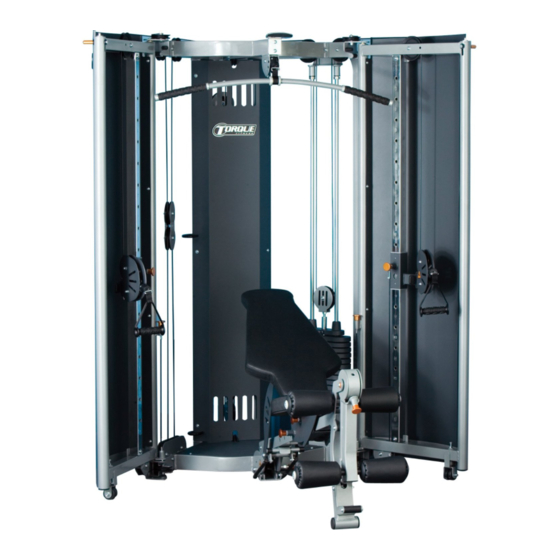
- Page 1 Fold Away Strength Trainer Assembly and Maintenance Guide Version: F5-01-001 Part #: 5099201-C...
-
Page 2: Table Of Contents
TABLE OF CONTENTS Important Safety Instructions …………………………………………………..3 Important Safety Instructions for Using the Equipment ………………...3 Important Safety Instructions for Assembling the Equipment ………….3 Obtaining Service ..............………….3 General Notes………………………………………………………………………4 Unpacking the Equipment………………………………………………….4 Tools Required………………………………………………………………4 Optional Equipment…………………………………………………………4 Assembly Tips……………………………………………………………….4 Parts List…………………………………………………………………………….5-6 Assembly Instructions……………………………………………………………6-44 Adjustments and Maintenance………………………………………………….41,44 Cable Adjustments………………………………………………………….41 Attachment and Adjustment Instructions…………………………………44... -
Page 3: Important Safety Instructions
Do not disassemble, remove any parts or components or otherwise attempt to repair this product. DO NOT use product if product appears damaged. DO NOT attempt to fix a broken or jammed machine, obtain assistance from your authorized Torque Fitness Dealer. Failure to comply with these instructions will void any and all product warranties. -
Page 4: General Notes
Failure to do so may result unit from or call Torque Fitness Customer Service. A 6-inch scale is provided at the bottom of in clearance issues and will degrade the every assembly instruction page. -
Page 5: Parts List
Parts List PART NO. DESCRIPTION PART NO. DESCRIPTION 50084PA BASE 5099401 BASE END CAP 50725PA RIGHT SIDE 50731PA RIGHT DOOR 50720PA LEFT SIDE 50270PA WHEEL SUPPORT 2001826 1/2 X 7” BUTTON HEAD BOLT 50741PA LEFT DOOR 2001816 1/2 X 4-1/2” BUTTON HEAD BOLT 5059701 SLIDE UPRIGHT 2001806... - Page 6 WEIGHT STACK SELECTOR FORK 5101001 ORANGE PIVOT WASHER 5093101 WEIGHT STACK LABEL 2002905 3/8 X 1-3/4” HEX HEAD BOLT 5098201 RUBBER BUMPER 5101301 F5 WALLCHART 5095301 SHAFT COLLAR 5101501 GUIDE ROD LUBE 5070701 ROLLER PAD INSERT 5110001 SILVER TOUCH UP PAINT 5049701...
- Page 7 STEP 1 LOOSELY assemble the RIGHT SIDE (2) to the BASE (1) using: Three 3/8 X 2-3/4” BOLTS (13) One 3/8 X 2-1/2” BOLT (15) Eight 3/8” WASHERS (29) Four 3/8” LOCK NUTS (25) LOOSELY assemble the LEFT SIDE (3) to the BASE (1) using: Three 3/8 X 2-3/4”...
- Page 8 STEP 2 LOOSELY assemble the TOP BOOM (33) between the RIGHT and LEFT SIDES (2 & 3) using: Six 3/8 X 2-3/4” BOLTS (13) Twelve 3/8” WASHERS (29) Six 3/8” LOCK NUTS (25) 3/8 X 2-3/4” 13 Page 8...
- Page 9 STEP 3 LOOSELY assemble the UPRIGHT SUPPORT PLATE (34) between the rear tubes of the RIGHT and LEFT SIDES (2 & 3) using: Four 3/8 X 2-3/4” BOLTS (13) Eight 3/8” WASHERS (29) Four 3/8” LOCK NUTS (25) 13 3/8 X 2-3/4” SECURELY TIGHTEN ALL LOOSE FRAME CONNECTIONS MADE TO THIS POINT.
- Page 10 STEP 4 3/8 X 3/4” 19 Insert one WHEEL SUPPORT (37) into the bushing on the bottom of the RIGHT DOOR (36) as shown. LOOSELY assemble the RIGHT DOOR (36) to the RIGHT SIDE (2) using: Two 3/8 X 3/4” BOLTS W/NP (19) RETAINING Two 3/8”...
- Page 11 STEP 5 19 3/8 X 3/4” Insert one WHEEL SUPPORT (37) into the bushing on the bottom of the LEFT DOOR (38) as shown. LOOSELY assemble the LEFT DOOR (38) to the LEFT SIDE (3) using: Two 3/8 X 3/4” BOLTS W/NP (19) RETAINING Two 3/8”...
- Page 12 STEP 6 To level the RIGHT and LEFT DOORS (36 & 38), thread one 3/8 X 2” BUTTON HEAD BOLT (17) and one 3/8” JAM NUT (26) into the top of DOOR LOCK the bushing on the RIGHT DOOR (36). ANGLE Turn the bolt clockwise until the wheel touches the floor and the door is able to rotate in and out...
- Page 13 STEP 7 Pull back spring pin on the RIGHT SLIDE (40) and CAREFULLY slide assembly over the end of the SLIDE UPRIGHT (39). Release spring pin into tenth hole on the SLIDE UPRIGHT (39). Note: Ensure numbers on the Slide Upright show through the hole in Slide.
- Page 14 STEP 8 SECURELY assemble the SLIDE UPRIGHT (39) to the RIGHT DOOR (36) using: Two 3/8 X 2-3/4” BOLTS (13) Four 3/8” WASHERS (29) Two 3/8” LOCK NUTS (25) Note: make sure the numbers on the SLIDE UPRIGHT are facing in towards the mach- ine.
- Page 15 STEP 9 Pull back spring pin on the LEFT SLIDE (41) and CAREFULLY slide assembly over the end of the SLIDE UPRIGHT (39). Release spring pin into tenth hole on the SLIDE UPRIGHT (39). Note: Ensure numbers on the Slide Upright show through the hole in Slide.
- Page 16 STEP 10 SECURELY assemble the SLIDE UPRIGHT (39) to the LEFT DOOR (38) using: Two 3/8 x 2-3/4” BOLTS (13) Four 3/8” WASHERS (29) Two 3/8” LOCK NUTS (25) Note: make sure the numbers on the SLIDE UPRIGHT are facing in towards the mach- 13 3/8 X 2-3/4”...
- Page 17 STEP 11 Insert two GUIDE RODS (42) into the bracket on the LEFT SIDE (3) Lubricate GUIDE RODS (42) using the GUIDE ROD LUBE (87) provided SELECTOR Slide two RUBBER BUMPERS (74) down over STOP the GUIDE RODS (42) CAREFULLY slide nineteen WEIGHT PLATES (71) down over the GUIDE RODS (42) FLANGE SPACERS...
- Page 18 STEP 12 SECURELY assemble the GUIDE ROD SUP- PORT (43) to the top of the LEFT SIDE (3), using: Two 3/8 x 3” BOLTS (12) 3/8 X 3” 12 Four 3/8” WASHERS (29) Two 3/8” LOCK NUTS (25) Slide the two SHAFT COLLARS (75) up to the GUIDE ROD SUPPORT (43) and SECURELY tighten the set screws.
- Page 19 STEP 13 SECURELY assemble the BENCH SWIVEL (44) to the BASE (1) using: Two 1/2 X 1-1/2” BOLTS (7) Two 1/2” WASHERS (28) Two 1/2” LOW HEIGHT LOCK NUTS (23) Note: Make sure BENCH SWIVEL (44) Ro- tates freely, then engage pull pin into lower slot.
- Page 20 STEP 14 Pull back spring pin on the SEAT SLIDE (68) and CAREFULLY slide assembly over the BENCH FRAME (45) as shown. Release spring pin into the front adjustment SPRING PIN hole on the BENCH FRAME (45). FRONT ADJUSTMENT HOLE Page 20...
- Page 21 STEP 15 (Note: Pull pin on BENCH SWIVEL (44) must be engaged in lower slot of BASE (1) prior to this step.) SECURELY assemble the BENCH FRAME (45) to the BENCH SWIVEL (44) using: Two 3/8 x 4” BOLTS (8) Four 3/8”...
- Page 22 STEP 16 SECURELY assemble the ADJUSTMENT SUPPORT (46) to the BENCH FRAME (45) using: Two 3/8 X 2-3/4” BOLTS (13) Four 3/8” WASHERS (29) Two 3/8” LOCK NUTS (25) 3/8 X 2-3/4” 13 Page 22...
- Page 23 STEP 17 SECURELY assemble the BACK PAD AD- JUST (47) to the ADJUSTMENT SUPPORT (46) using: One 1/2 x 7” BOLT (4) Two 1/2” WASHERS (28) One 1/2” LOCK NUT (22) Note: Securely tighten connection then back nut off ¼ turn. 1/2X 7”...
- Page 24 STEP 18 SECURELY assemble the BACK PAD SUP- PORT (48) to the SEAT SLIDE (68) on the BENCH FRAME (45) using: One 1/2 x 4-1/2” BOLT (5) Two 1/2” WASHERS (28) One 1/2” LOCK NUT (22) Note: Securely tighten connection then back nut off ¼...
- Page 25 STEP 19 SECURELY assemble the LEG CURL/ EXTENION PIVOT (49) between the plates on the BENCH FRAME (45) using: Two 3/8 X 3/4” BOLTS W/NP (19) Two ORANGE PIVOT WASHERS (84) ORANGE 3/8 X 3/4” 19 Page 25...
- Page 26 STEP 20 SECURELY assemble the SEAT PAD (51) to the SEAT SUPPORT BRACKET (50) using: Two 3/8 x 1-1/4” BOLTS (16) Two 3/8” WASHERS (29) 3/8 X 1-1/4” 16 Page 26...
- Page 27 STEP 21 SECURELY assemble the SEAT SUPPORT BRACKET (50) to the SEAT SLIDE (68) on the BENCH FRAME (45) using: One 3/8 x 5” BOLT (14) Two 3/8” WASHERS (29) One 3/8” LOCK NUT (25) Note: Securely tighten connection then back nut off ¼...
- Page 28 STEP 22 SECURELY assemble the BACK PAD (52) to the BACK PAD SUPPORT (48) using: Two 3/8 x 3” BOLTS (12) Two 3/8” WASHERS (29) Insert four ROLLER PAD INSERTS (76) into each end of the two ROLLER PADS (54) as shown in inset Assemble the two ROLLER PADS (54) and the ROLLER PAD SUPPORT (53) to the BENCH...
- Page 29 STEP 23 CAREFULLY LIFT AND ROTATE THE BENCH INTO ITS UPRIGHT AND STORED POSISTION. ENGAGE SPRING PIN INTO LOCKED POSISTION. Assemble two GAS SHOCKS (77) to the BASE (1) and ADJUSTMENT SUPPORT (46) (one on each side) by gently snapping them over the studs on the Base and Adjustment Support NOTE: To ensure proper function of the BENCH...
- Page 30 STEP 24 Holding the cable end parallel with the floor and with the bolts facing up and down, carefully remove the bolts from the FAST ATTACH CABLE COUPLER from one end of the UPPER CABLE (57) as shown. Slide the HOUSING away from the SLIDE and remove the ball end of the cable from the COU- PLER CORE.
- Page 31 STEP 25 1/2 X 2” 6 SECURELY assemble one 1/2 X 2” BOLT (6) and one 1/2” JAM NUT (24) to the 4-1/2” PUL- LEY BRACKET (83) as shown in inset. STEM Thread one additional 1/2” JAM NUT (24) onto the end of the 1/2 X 2”...
- Page 32 STEP 26 Continue to route the ball end of the UPPER CABLE (57) around the pulleys of the PULLEY BRACKET (56), RIGHT SIDE (2), DUAL FLOATING PULLEY (55), RIGHT DOOR (36) and thru the RIGHT SLIDE (40) as shown. Re-assemble the FAST ATTACH CABLE COUPLER to the ball end of the UPPER CABLE (57) using the following steps:...
- Page 33 STEP 27 Remove one of the two jam nuts from each threaded stud of the LOWER CABLE (58). Attach one end of the cable to the RIGHT SLIDE (40) as shown. Leave a 1” gap between the threaded stud and angle of the RIGHT SLIDE (40).
- Page 34 STEP 28 Continue routing LOWER CABLE (58) up and around bottom pulley of the DUAL FLOATING PULLEY (55). Pulley will need to be removed to route cable around it. SECURLEY tighten bolt when finished. Continue to route LOWER CABLE (58) through the RIGHT SIDE (2) and BASE (1) as shown.
- Page 35 STEP 29 Continue to route LOWER CABLE (58) through the BASE (1), LEFT SIDE (3) and up through the LEFT DOOR (38) as shown SECURELY assemble one 4-1/2” PULLEY (78) to the LEFT SIDE (3) and one 3-1/2” PULLEY (79) to the LEFT DOOR (38) as shown using: Two 3/8 X 1-3/4”...
- Page 36 STEP 30 Make sure that the cable is in the groove of the pulley and is running Disassemble the two BOLTS on the FAST HOUSING underneath cable retain- ATTACH CABLE COUPLER from the end of BOLT COUPLER ing pin. the LAT CABLE (59) as shown CORE SPRING 3/8 X 2-1/4”...
- Page 37 STEP 31 Attach the threaded end of the LEG CURL/EXT CABLE (60) to the threaded post on the PUL- LEY BRACKET (56). Leave a 1” gap between the threaded stud and the post of the PULLEY BRACKET (56), and then tighten securely up against the post.
- Page 38 STEP 32 Wrap the LEG CURL/EXT CABLE (60) around one 3-1/2” PULLEY (79) and SECURELY assemble the pulley to the BASE (1) using: One 3/8 X 2” BOLT (17) One CABLE RETAINING BRACKET (90) Two 3/8” WASHERS (29) One 3/8” LOCK NUT (25) Continue routing LEG CURL/EXT CABLE (60) up and around bottom pulley of the DUAL EXISTING...
- Page 39 STEP 33 Continue to route the LEG CURL/EXT CABLE (60) through the front tube and under the pre- assembled 3-1/2” pulley on the front of the BASE (1). Once the cable has been routed, SECURELY assemble the cable retaining 3/8 X 3-1/4” 11 hardware to the hole under the pulley on the plates of the BASE (1) using: One 3/8 X 3-1/4”...
- Page 40 STEP 34 Continue to route the LEG CURL/EXT CABLE (60) through the BENCH FRAME (45) as shown. SECURELY Assemble the swivel end of the LEG CURL/EXT CABLE (60) to the LEG CURL/ EXT PIVOT (49) using: 3/8 X 3-3/4” 9 One 3/8 X 2”...
-
Page 41: Cable Adjustments
STEP 35 CABLE ADJUST POINT TO ADD/REDUCE CABLE TENSION Note: Prior to adjusting cable tension, adjust doors all the way out. Position SWIVEL PULLEY cable ends horizontal or CABLE parallel with the floor. ADJUST POINT (2X) Adjust the tension in the cables by tightening or loosening the jam nuts on the threaded ends of the cables at the cable adjustment points as shown. - Page 42 STEP 36 SECURELY assemble the REAR SHROUD (61) to the rear tubes of the RIGHT and LEFT SIDES (2 & 3) using: Six 1/4 X 1/2” BOLTS (21) Six 1/4” WASHERS (31) 21 1/4 X 1/2” Page 42...
- Page 43 DOOR (38) using: Eight 1/4 X 1/2” BOLTS (21) Eight 1/4” WASHERS (31) Thank you for purchasing the TORQUE FITNESS F5 FOLD AWAY STRENGTH TRAINER For customer service, call your local authorized Torque Fitness Dealer or 1-877-TORQUE5 (1-877-867-7835) or outside the U.S.
-
Page 44: Maintenance
STEP 38 ACCESSORIES To attach the STRAP HANDLES (62), LAT BAR (63) and UNIVERSAL ADPAPTER (64) simply insert ADAPTER into the end of the FAST ATTACH CABLE COUPLER until it clicks. To remove the attachment, push up on the CABLE COUPLER to release the ADAPTER. - Page 45 Page 45...
-
Page 46: Assembly Checklist
Fold Away Strength Trainer Assembly Checklist (THIS CHECKLIST MUST BE FILLED OUT IN ITS ENTIRETY AND LEFT WITH THE OWNER) Product Serial Number _______________________________ Date Assembled _____________ Authorized Dealer _________________________ Assembler(s) __________________________ POST ASSEMBLY ADJUSTMENTS / CHECKS: _______ Ensure ALL connections are tightened according to the instructions. _______ Cable Tension Adjustment (see step 35): ensure that the head plate rests on the first weight plate yet there is not a lot of slop in the cable system. - Page 47 LIMITATION OF LIABILITY This Limited Warranty Offer (“Offer”) states the terms and conditions upon which Torque Fitness, LLC (“We” or “Us”) extends a non-assignable LIMITED WARRANTY only to the original owner (“You”) of the Torque Fitness product (“Product”). The warranty terms apply to in home use only. By purchasing the Product, You accept all terms and conditions of this Offer.
- Page 48 OR DAMAGES OR DEFECTS IN THE PRODUCT CAUSED OR CONTRIBUTED TO BY ANY CAUSE EXTERNAL TO THE PRODUCT. Any Product misuse, abuse, placement in any application other than in home use, or alteration, any attempt to repair by a person other than an authorized Torque Fitness Service Center, any improper assembly, accident, or any other condition resulting from occurrences beyond Our control will void this LIMITED WARRANTY.
- Page 49 PLACE STAMP HERE Torque Fitness 13750 Crosstown Drive NW Suite 204 Andover, MN 55304 FOLD HERE...
Need help?
Do you have a question about the F5 and is the answer not in the manual?
Questions and answers
I **** looking for the part number to the bottom base. The bracket on the back of mine that holds the pulley sheared off
The part number for the bottom base of the Torque Fitness F5 is 50084PA.
This answer is automatically generated