Table of Contents
Advertisement
Advertisement
Table of Contents

Subscribe to Our Youtube Channel
Related Manuals for FONESTAR ZSC-1110


Summary of Contents for FONESTAR ZSC-1110
- Page 1 ZS -1110 PA ZONE SYSTEM INSTRUCTION MANUAL...
- Page 2 We take this opportunity to thank you for buying this product. We recommend you read the instruction manual before switching on the machine and follow the instructions that are given. Keep the manual for future reference. SECURITY AND THE ENVIRONMENT ELECTRICAL SECURITY Check that the current in the mains connection where the machine is to be installed corresponds to the power supply of the machine.
-
Page 3: Exemption Of Liability
The characteristics of the equipment and the content of the manual can change without forewarning. FONESTAR, S.A. does not assume responsibilities regarding the inappropriate use of the equipment or the information supplied in this instruction manual, and specifically disclaims any implied liability for marketability or fitness for any other use. -
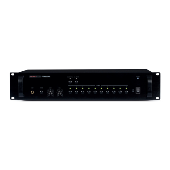
Page 4: Controls And Functions Front Panel
DESCRIPTION - 10 zone switching unit for 100 V line. - Extendable to 300 loudspeaker zones with additional ZSC-1110 units. - Suitable for PA installations of any size. - LED switching matrix status indicators. - Musical chimes. - Connection of up to 16 paging microphones ZS-11. -
Page 5: Rear Panel
REAR PANEL 1.- Socket: AC power supply socket. 2.- MUSIC IN CH 1-CH 10: 100 V background music amplifier input for zones 1-10, euroblock connectors. 3.- ALARM IN CH 1-CH 10: 100 V paging amplifier input for zones 1-10, euroblock connectors. 4.- ADDRESS: system identifier configuration selectors. - Page 6 13.- ALARM OUT A/B: alarm output contacts. These contacts close automatically when the ALARM IN A/B input contacts are closed. NOTE: if you have more than one ZSC-1110 zone system, it is recommeded that the ALARM OUT A/B output is connected to the ALARM In A/B input of the following zone system.
-
Page 7: Alarm Paging
In order to connect the mod. ZS-11 microphone, Cat 5e type control cable is used. This cable is connected to the COM socket on the zone system mod. ZSC-1110 and on the COM socket of the first microphone mod. ZS-11. -
Page 8: Connection Example
CONNECTION EXAMPLE In this configuration an amplifier for background music has been connected to another one for paging in the 10 zones in the system. The power of each amplifier must be equal to the power of the set of speakers in all the zones. -
Page 9: Control Cable
CONTROL CABLE Cat 5e or Cat 6 cable must be used to connect the microphone with the PA switchboard or several microphones in cascade. This cable is composed of 8 conductors which must be connected according to the previous diagram and both end in RJ-45 connectors (8P8C). For example, the following colour code can be used: Connector A: 1- Blue... -
Page 10: Technical Specifications
TECHNICAL SPECIFICATIONS ZSC-1110 CHARACTERISTICS 10-zone switching unit for 100 V line. Extendable to 300 loudspeaker zones with additional ZSC-1110 units. Suitable for PA installations of any size. LED switching matrix status indicators. Musical chimes. Connection of up to 16 paging microphones ZS-11. -
Page 11: Warranty
2 months after being conscious of the problem. It is only necessary to contact FONESTAR if it is impossible or imposes an undue burden for them to solve it. To benefit from this warranty it is necessary to show the proof of purchase with the date clearly visible, with no corrections or crossing out. - Page 12 www.fonestar.com...
Need help?
Do you have a question about the ZSC-1110 and is the answer not in the manual?
Questions and answers