YOKOGAWA PH8EFP User Manual
Kcl filling type ph sensor
Hide thumbs
Also See for PH8EFP:
- User manual (53 pages) ,
- User manual (67 pages) ,
- User manual (39 pages)

Related Manuals for YOKOGAWA PH8EFP


Summary of Contents for YOKOGAWA PH8EFP
- Page 1 User’s Manual Model PH8EFP KCl Filling type pH Sensor IM 12B7J1-01E IM 12B7J1-01E 12th Edition...
-
Page 2: Introduction
< Introduction > INTRODUCTION This manual covers the PH8EFP KCl Filling type pH Sensor. Other related items are described in the following manuals. Model Title IM No. PH8HG Guide-pipe Holder IM 12B7M2-01E PH8HF, PH8HFF Flow-Through Type Holder IM 12B07N01-01E... -
Page 3: For The Safe Use Of This Equipment
The product is provided on an “as is” basis. YOKOGAWA shall have neither liability nor responsibility to any person or entity with respect to any direct or indirect loss or damage arising from using the product or any defect of the product that YOKOGAWA can not predict in advance. IM 12B7J1-01E... - Page 4 Any option code is available. For PH202S, model and suffix code below is available. PH202S-○-E ○ must be C or U. There are no PH202S models that meet the Korean explosion proof standards. Any option code is available. Upper limit of process temperature on the PH8EFP Transmitter used in FLXA21 PH202S combination Ambient temperature Ta 40°C...
- Page 5 < Introduction > Other warnings are provided in the following. WARNING Handling precautions: (1) Potential electrostatic charging hazard Electrostatic charge may cause an explosion hazard. Avoid any actions that cause the generation of electrostatic charge, e.g., rubbing with a dry cloth.
-
Page 6: After-Sales Warranty
• If we replace the product with a new one, we won’t provide you with a repair report. • Yokogawa warrants the product for the period stated in the pre-purchase quotation Yokogawa shall conduct defined warranty service based on its standard. When the customer site is located outside of the service area, a fee for dispatching the maintenance engineer will be charged to the customer. - Page 7 Blank Page...
-
Page 8: Table Of Contents
< CONTENTS > Model PH8EFP KCl Filling type pH Sensor IM 12B7J1-01E 12th Edition CONTENTS INTRODUCTION .....................i For the safe use of this equipment .............ii After-sales Warranty ..................v Specification ..................... 1-1 1.1 Standard Specifications ................... 1-1 1.2 Model and Suffix codes ..................1-3 External Dimensions .................. - Page 9 viii < CONTENTS > 3.2.3 Replacing O-rings for Glass Electrode ..........3-3 Customer Maintenance Parts List ........CMPL 12B05J01-02E Customer Maintenance Parts List ........CMPL 12B05J01-02E Revision Information ....................i IM 12B7J1-01E 12th Edition : Dec.14,2018-00...
-
Page 10: Specification
< 1. Specification > Specification The Model PH8EFP KCl filling type pH Sensor permits stable pH measurement even for solutions having comparatively severe properties. This sensor can be mounted on either an PH8HF flow-through holder or an PH8HS submersion holder, or its can be used alone suspended in the solution (maximum depth 3 meters) depending on the specification. 1.1 Standard Specifications Measurement: Hydrogen ion concentration (pH) of a solution Measurement principle: Glass electrode method... - Page 11 If you have any questions about the wetted part construction of the product, be sure to contact Yokogawa. IM 12B7J1-01E...
-
Page 12: Model And Suffix Codes
< 1. Specification > 1.2 Model and Suffix codes pH Sensor Option Model Suffix Code Description Code PH8EFP ............KCl Filling Type pH Sensor Cable Length ....and KCl Tube ........Length ....10 m ....15 m ....20 m ....For Variopin connector 3m (*11) .... - Page 13 KCl powder (three bags, 250 mL solution each) /TMP Thermometer (0 to 100 °C) Including the following: Two 200 mL polyethylene cups One cleaning bottle Either /KCLL or /KCLP is required for PH8EFP-¨¨-¨¨-TT2. Consumables Part Part Name Remarks Number K9142TN...
-
Page 14: External Dimensions
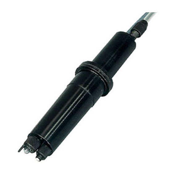
KCl solution tube KCl solution tube For FLXA202, FLXA21 (PH8EFP-��-��-TT�-N-E*A) Pin terminal (-E) For PH200, PH400 (PH8EFP-��-��-TT�-N-T*A) For PH100 (PH8EFP-��-��-TT�-N-B*A) Ø27.5 Ø27.5 Ø38 Ø38 Fork terminal (-T, -B) Figure 1.1 PH8EFP Filling type pH Sensor IM 12B7J1-01E 12th Edition : Dec.14,2018-00... - Page 15 < 1. Specification > General Purpose KCl Reserve Tank Midium Pressure KCl Reserve Tank (PH8EFP - □□ - □□ - TT1 - □ -□ *A) (PH8EFP - □□ - □□ - TT2 - □ -□ *A) Pressure gauge Socket type connector Rc1/4 screw JIS 50A pipe ø60.5...
-
Page 16: Installation
2.1.1 Unpacking and Inspection The Model PH8EFP pH sensor is well packed so as to prevent damage during shipment. After removing the sensor from its shipping container, visually check the sensor for damage. Check also the order was delivered correctly by identifying the information on the nameplate attached on the sensor body. -
Page 17: Mounting Glass Electrode
< 2. Installation > 2.1.2 Mounting Glass Electrode Mount the glass electrode on the sensor body as per the following procedure: (1) Peel off the seal from the electrode mounting hole on the sensor body. (2) Remove the cap for the glass membrane. Wipe off any solution remaining on the O-ring with a tissue or other material. (3) Remove the cap for the gold-plated pin. (4) Confirm that there is no damage on the O-ring that might affect its sealing performance. (5) Mount the glass electrode on the sensor body. -
Page 18: Requirements For Mounting The Ph Sensor
(3) If specified, a reserve tank containing 250 mL KCl solution and mounting hardware to hold this tank are supplied with the PH8EFP pH sensor. Attach the holding hardware to the pipe (nominal diameter 50 mm). Connect the reserve tank to the KCl solution supply tube of the sensor. Remove the cap from the tank and screw the tube connector securely into the tank. - Page 19 < 2. Installation > Sensor Cable Cable Clamp Attaching "Stopper" Sensor Cable 2-inch (60.5 mm O.D) Stopper Mounting Pipe Arm Pipe Guide Pipe 20 to 30 mm pH Sensor Figure 2.4 Mounting Sensor in Guide Pipe IM 12B7J1-01E 12th Edition : Dec.14,2018-00...
-
Page 20: Installing Sensor In Ph8Hs Submersion Holder
< 2. Installation > 2.2.2 Installing Sensor in PH8HS Submersion Holder To install the sensor in the submersion holder, proceed as follows: (1) Pass the sensor cable through the sensor holder. If the submersion holder remains installed, remove the sensor holder in any case. For a pipe-mounting submersion holder without a cleaner, loosen the sensor holder nut to remove the holder. - Page 21 < 2. Installation > Clamp (Screw) Cleaner Holder Sensor Holder F2.7.ai Figure 2.7 Removal of Sensor Holder (with Cleaner) To install the sensor cable in the sensor holder, first remove the protector screwed onto the sensor holder end and then remove the protective foam piece (for shipping; thus, it is not necessary after the sensor is installed in the holder). Pass the sensor cable through the O-ring then attach the O-ring to the sensor flange (see Figure 2.7).
- Page 22 (4) If specified, a reserve tank containing 250 mL KCl solution and mounting hardware to hold this tank are supplied with the PH8EFP pH sensor. Attach the mounting hardware to the pipe (2-inch). Connect the reserve tank to the KCl solution supply tube of the sensor. Remove the cap from the tank and screw the tube connector securely into the tank.
-
Page 23: Installing Sensor In Flow-Through Holder
< 2. Installation > pH Sensor O-ring Protector F2.9.ai Figure 2.9 Installing Sensor in Submersion Holder (7) Close the waterproof cap, and attach the holder to the arm pipe, flange or cleaner holder completely. 2.2.3 Installing Sensor in Flow-through Holder To install the sensor in a flow-through holder, proceed as follows: (1) Connect the sensor cable to the associated instrument. First, remove the sensor fixing nut and pass the sensor cable through the nut. pH Sensor Sensor Fixing Nut Figure 2.10 Preparation for Sensor Cable Connection Properly connect the sensor cable by referring to Section 2.3. - Page 24 < 2. Installation > (3) If specified, a reserve tank containing 250 mL solution and mounting hardware to hold this tank, or a medium pressure reserve tank are supplied with the PH8EFP pH sensor. Attach the mounting hardware for general purpose reserve tank to a pipe (2-inch). Connect the general purpose reserve tank to the KCl solution supply tube of the sensor. Remove the cap from the tank and screw the tube connector securely into the tank.
- Page 25 2-10 < 2. Installation > Cover Reserve Tank Fixing Nut KCl Solution To pH Sensor Refilling Tube F2.11.1.ai Figure 2.11.1 Big-Volume Reserve Tank (5) Connect the pH sensor to its holder. Remove the protective cap from the sensor. Also remove the protective foam piece (for shipping - this is not necessary after installing the sensor) from the holder.
-
Page 26: Ph Sensor Cable Wiring Procedure
2-11 < 2. Installation > pH Sensor Cable Wiring Procedure 2.3.1 Processing of Cable Inlet Hole Open the cable inlet hole in terminal box using the supplied punch tool. The location of the cable inlet hole is shown by the circle-shaped groove under the case. The end of the supplied punch tool is put in the center of this circle and it is tapped with appropriate force. -
Page 27: Connecting Sensor Cable To Flxa202/Flxa21
2-12 < 2. Installation > Put the nut in place, and screw it onto the main body sufficiently. At this time, loosen the cap so that the cable is not twisted. After fixing the main body, tighten the cap to keep moisture out of the equipment. However if the cap is screwed up too tight, the cable will be damaged. Attach the nut in the direction shown here (so that it engages the detent groove). Gasket Main unit F2.15.ai... -
Page 28: Connecting Sensor Cable To Flxa402
2-13 < 2. Installation > (3) Install the cable gland in the wiring hole as follows: Pass the tip of the cable gland into the opening and completely tighten the gland with the nut inside the case. After tightening the gland, secure the cap properly to prevent moisture from getting into the case. - Page 29 Blank Page...
-
Page 30: Maintenance On Operation
< 3. Maintenance on operation > Maintenance on operation Operation and Periodic Maintenance 3.1.1 Calibrating pH Sensor Using Buffer Solutions Calibrate pH sensors with buffer solutions before starting normal operation because the emf of glass electrodes differs somewhat from each other. The emf of a glass electrode gradually changes due to electrode staining or deterioration. Therefore, buffer solution calibration must be carried out periodically within a given period of time to keep the measurement errors within the limits specified. For more detailed information on the calibration procedures, see relevant pH transmitter/ converter IMs . -
Page 31: Cleaning Glass Electrode And Liquid Junction
< 3. Maintenance on operation > (2) Remove the socket connector on the reserve tank and stop the air pressurizing the tank (see Figure 3.2). Socket type Connector Press this part, connector can be removed. F3.2.ai Figure 3.2 Socket Type Connector. (3) Remove the nut fixing the reserve tank cap and remove the cap. -
Page 32: Replacing Consumable Parts
O-ring inside the glass electrode. For individual replacement of the O-ring, use the one recommended by Yokogawa. When installing the O-ring, wind a slip of paper or tape around the thread part on the glass electrode so as not to scratch the O-ring. - Page 33 < 3. Maintenance on operation > O-ring (Ø9/Ø12) O-ring (Ø6/Ø9) Screw Before installing, wind a slip of paper or tape around the thread part to prevent scratches. Figure 3.5 Installing the O-ring IM 12B7J1-01E 12th Edition : Dec.14,2018-00...
- Page 34 6 mm ID. ᵡ 9 mm OD. K9142QS K9142PJ Length 3 m for general use, 9 mm ID. ᵡ 12 mm OD. K9319RB for PH8EFP/PF, 6 mm ID. ᵡ 9 mm OD. K9142PK Length 5 m K9319RC K9142NM Length 7 m for PH8EFP/PF, 9 mm ID.
- Page 35 Medium Pressure KCl Reserve Tank Assembly for Suffix Code: -TT2 ( K9142VG ) To KCI Filling Tube Item Part No. Description K9142VL Tank Assembly K9142VJ Block K9142VK Block G9303AE O-Ring L9835DD Joint L9867BS Pressure Gauge K9142RU Label K9142VP Bracket K9142EJ K9142VQ Ring L9826AL...
- Page 36 Revision Information Title : Model PH8EFP KCl Filling type pH Sensor Manual No. : IM 12B7J1-01E Dec. 2018/12th Edition Added -V (Variopin connecter) P i, P1-1, 1-3, 1-5, 1-6, 2-1, 2-6, 2-10, 2-13, CMPL Nov. 2018/11th Edition Added FLXA402, P i, P1-3. Jan. 2016/10th Edition Change of KCl solution consumption P1-2, P3-1.
- Page 37 Yokogawa Electric Corporation 2-9-32 Nakacho, Musashino-shi, Tokyo 180-8750, JAPAN http://www.yokogawa.com/ IM 12B7J1-01E 12th Edition : Dec.14,2018-00...
Need help?
Do you have a question about the PH8EFP and is the answer not in the manual?
Questions and answers