Table of Contents
Advertisement
Quick Links
PLEASE RETAIN
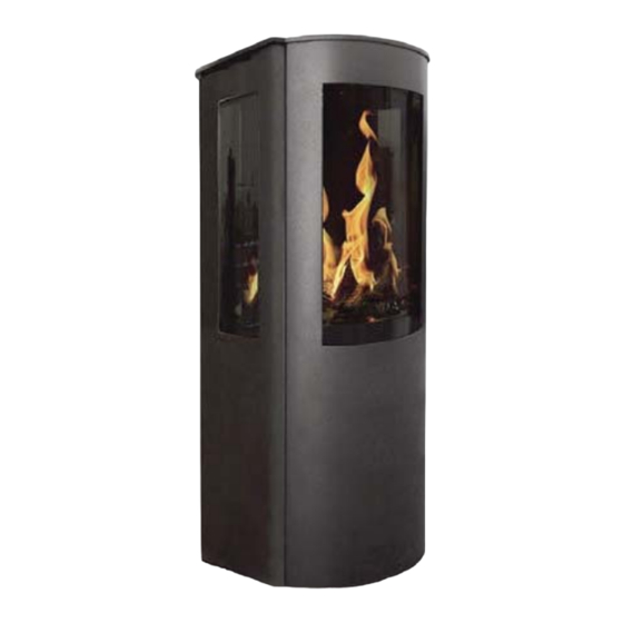
Argon F500 Gas
Models
F500 OVAL
F500 SLIM
INSTALLATION AND OPERATING INSTRUCTIONS
This appliance is hot while in operation and retains its heat for a long period of time after use. Children,
aged or infirm persons should be supervised at all times and should not be allowed to touch the hot
working surfaces while in use or until the appliance has thoroughly cooled.
To ensure safety, satisfaction and reliable service, this appliance must be installed by a suitably qual-
ified and component person.
Advertisement
Table of Contents

Related Manuals for Stanley Argon F500 OVAL


Summary of Contents for Stanley Argon F500 OVAL
- Page 1 PLEASE RETAIN Argon F500 Gas Models F500 OVAL F500 SLIM INSTALLATION AND OPERATING INSTRUCTIONS This appliance is hot while in operation and retains its heat for a long period of time after use. Children, aged or infirm persons should be supervised at all times and should not be allowed to touch the hot working surfaces while in use or until the appliance has thoroughly cooled.
-
Page 2: Table Of Contents
Stanley Stove Warranty ........ - Page 3 TABLE OF CONTENTS PAGE NO. 43. Wiring Diagram ..............23 44.
-
Page 4: Stanley Stove Warranty
CONDITIONS OF WARRANTY Your Stanley Stove is guaranteed against any part that fails (under normal operating conditions) for a two year period from the date of installation of the appliance. If the unit is not installed within six months of date of purchase, the war- ranty will commence six months from the date of purchase. -
Page 5: Important Operation/ Maintenance Notes
IMPORTANT OPERATION / MAINTENANCE NOTES Now that your Stanley Stove is installed and no doubt you are looking forward to the many comforts it will pro- vide, we would like to give you some tips on how to get the best results from your unit. -
Page 6: Commissioning Checklist
COMMISSIONING CHECK LIST FLUE SYSTEM PASS FAIL 1. Flue Routing in compliance with Guidelines (see Flue Installation) 2. Waterford Stanley Flue Pipes & Fittings Used. 3. Flue Terminal positioned correctly & clear of obstructions. LOCATION PASS FAIL 1.Clearance to combustible materials must be adhered to (see Clearance to Combustible section). -
Page 7: Installation & Operating Instructions
RGI Registered Installer (ROI) or a Gas Safe Installer (NI or UK) or equivalent. Your Stanley Gas stove is supplied with the following items: It is important to note that once a type of gas has •... -
Page 8: Floor Protection
B.S. 1387 - Steel tubes. Fig.1 B.S. 6362 - stainless steel tubes. B.S. 1740 - Wrought steel pipes. B.S. 4089 - L.P.G. hoses and assemblies. METERS A suitable gas meter must be connected to the ser- vice pipe either by a representative of the gas board or by an appointed contractor. -
Page 9: Gas Soundness Testing
The flue system must be constructed from The table below details the list of Waterford Stanley the appliance upwards, with all joints being Approved Flue Fittings for this stove. - Page 10 Fig.6 Fig.5 Fig.7 Terminal Position Distance Terminal Position Distance (mm) (mm) A* Directly below an opening, air brick, Above ground roof or balcony level opening window etc. Above an opening, air brick, opening win- From a surface facing the terminal dow etc.
-
Page 11: Fuel Bed Arrangement
FUEL BED ARRANGEMENT Scatter the bags of embers over the top of the burners as shown in Fig 11 keeping the NOTE: When arranging the Media into the pilot area & second thermocouple clear. Firebed, it is important that the Pilot Area Position Logs S1, S2 &... -
Page 12: Stove Dimensions
Fig.14 Fig.15 Log S7 Fircone / Log S6 Log S8 STOVE DIMENSIONS F500 OVAL 1060 F500 SLIM Note: Dimensions stated are in millimetres unless otherwise stated and may be subject to a slight +/- variation. -
Page 13: Commissioning The Stove
COMMISSIONING THE STOVE The Appliance Commissioning Checklist (see Page Fig.16 6) must be filled out in conjunction with conducting the following checks: Pilot Ignition Check Ignite the pilot light as described in the Remote Control Operation Section. Check that the pilot light flame stays light. Extinguish the pilot light. -
Page 14: Technical Data
TECHNICAL DATA NATURAL GAS Gas Type Supply Pressure mbar Nominal Heat Input Gross (Hs) Nominal Heat Input Nett (Hi) Consumption 0.796 0.796 Burner Pressure (hot) mbar Maximum Heat Output Minimum Heat Output Injector Marking 320 (Front) / 280 (Rear) Pilot 446.1385.44 Efficiency Class/Efficiency 2 / 81%... -
Page 15: Remote Control Operation
REMOTE CONTROL OPERATION TEMPERATURE COUNTDOWN BUTTON TIMER UP ARROW POWER BUTTON PROGRAM DOWN ARROW BUTTON ECO BUTTON REAR BURNER BUTTON NOTE: If not using the mains adapter, it is recommended that the batteries are replaced in the gas control box at the beginning of the heating season (see Battery Replacement Section). The control box will provide frequent beeps for 3 seconds when the batteries are low. -
Page 16: Setting Celsius Or Fahrenheit
The flame height can also be adjusted to the two Fig.23 preset flame heights by: Low Fire (LO) - Double Click the Down Arrow Button - see Fig 21. High Fire (HI) - Double Click the Up Arrow Button - see Fig 22. To turn off the stove, press &... -
Page 17: Setting The Time
SETTING THE TIME Fig.27 Press the Up Arrow Button & Down Arrow Button simultaneously until the DAY flashes on the display - see Fig 25. Press the Up Arrow Button & Down Arrow Button to select the number that corresponds to the current day (e.g. -
Page 18: Program Mode
Program Mode Fig.28 The following procedure should be used when setting the Temperature and Timer Program: To set the temperature, press & hold the Program Button until Program Mode display flashes ON & the set temperature displayed. Then Program Mode display flashes OFF & the set temperature flashes (see... -
Page 19: Eco Mode
To activate the Program Mode, press the Program Fig.32 Button. The Program Mode Symbol will be displayed as shown in Fig 34. To deactivate the Program Mode & return to Manual Mode, press the Program Button and then press either the Up Arrow Button or Down Arrow Button. Eco Mode To activate the Eco Mode, press the Eco Button. -
Page 20: Countdown Timer
Countdown Timer Fig.37 The Countdown Timer allows for the Stove to be operated for a set period (up to maximum of 9 hours & 50 minutes) provided the Stove is set to Manual, Thermostatic or Eco Modes.To set the Countdown Timer: Press &... -
Page 21: Cleaning
Download the myfire App from Apple App Provision of an alarm must not be considered a Store or Google Play Store. substitute for either installing the appliance Start App setup. correctly or ensuring regular servicing and Choose language, temperature (Celsius or maintenance of the appliance and chimney Fahrenheit) and time format (12 or 24 hour). -
Page 22: Battery Replacement
BATTERY REPLACEMENT Fig.40 The Gas Valve Control Box requires four AA Batteries which are fitted by removing the front cover and inserting the batteries into the housing as shown in Fig 40. The Remote Control requires two AAA Batteries which are fitted by removing the back cover and inserting the batteries into the housing as shown in Fig 41. -
Page 23: Wiring Diagram
WIRING DIAGRAM... -
Page 24: Exploded View - F500 Oval
EXPLODED VIEW - F500 OVAL No. Description Part Number No. Description Part Number Complete Burner - Nat Gas SW-DB-2TC-NG 23 Pilot Assembly - Nat Gas SW-UMM-PLA-NG Complete Burner - LPG SW-DB-2TC-LPG Pilot Assembly - LPG SW-UMM-PLA-LPG Inner Flue Collar SW-PFC-INC-001 24 Electrode SW-UMM-EL-022 Outer Flue Collar... -
Page 25: Exploded View - F500 Slim
EXPLODED VIEW - F500 SLIM No. Description Part Number No. Description Part Number Complete Burner - Nat Gas SW-DB-2TC-NG 22 Outer Shell SW-SIH-OBW-021 Complete Burner - LPG SW-DB-2TC-LPG 23 Pilot Assembly - Nat Gas SW-UMM-PLA-NG Inner Flue Collar SW-PFC-INC-001 Pilot Assembly - LPG SW-UMM-PLA-LPG Outer Flue Collar SW-PFC-OFC-002... -
Page 26: Service Records
SERVICE RECORDS 1ST SERVICE 2ND SERVICE Date of Service:............Date of Service:............Next Service Due:............. Next Service Due:............. Signed: ..............Signed: ..............RGI/Gas Safe Registration No/Stamp: RGI/Gas Safe Registration No/Stamp: 3RD SERVICE 4TH SERVICE Date of Service:............Date of Service:............Next Service Due:............. -
Page 27: Fault Finding- General
FAULT FINDING - GENERAL ISSUE POSSIBLE CAUSE SOLUTION Remote Control Batteries Low. Replace Batteries (See Battery Replacement Section Gas Control Valve Batteries Low. Replace Batteries (See Battery Replacement Section Optional Mains Adapter not operat- Check Mains Adapter. Remote Control ing correctly. not working Check link between remote &... -
Page 28: Fault Codes - Remote Control
Bad Connection between Remote responding intermittently. Control & Burner. Battery Low on Gas Control Valve (See Battery Replacement Section.) Supplied by Waterford Stanley Ltd., Unit 401-403, IDA Industrial Estate, Cork Road, Waterford, Ireland. Tel: (051) 302300 Fax (051) 302315 N00787AXX Rev: 001...
Need help?
Do you have a question about the Argon F500 OVAL and is the answer not in the manual?
Questions and answers