Table of Contents
Advertisement
WARNING:
FIRE OR EXPLOSION HAZARD
Failure to follow safety warnings exactly could result in serious injury,
death, or property damage.
— Do not store or use gasoline or other flammable vapors and
liquids in the vicinity of this or any other appliance.
— WHAT TO DO IF YOU SMELL GAS
•
Do not try to light any appliance.
•
Do not touch any electrical switch; do not use any
phone in your building.
• Leave the building immediately.
• Immediately call your gas supplier from a neighbour's
phone. Follow the gas supplier's instructions.
• If you cannot reach your gas supplier, call the fire
department.
— Installation and service must be performed by a qualified
installer, service agency or the gas fitter.
DANGER
A barrier designed to reduce the risk of burns from the
hot viewing glass is provided with this appliance and
shall be installed for the protection of children and other
at-risk individuals.
Installation & Maintenance Manual
®
C
US
HOT GLASS WILL
CAUSE BURNS.
DO NOT TOUCH GLASS
UNTIL COOLED.
NEVER ALLOW CHILDREN
TO TOUCH GLASS.
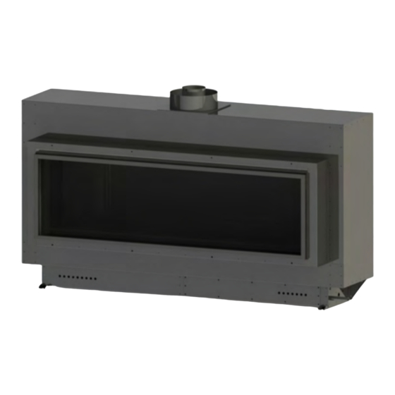
R Series
INDOOR GAS FIREPLACE
R320 50,000 BTU/hr Natural Gas or Propane Gas
R420 65,000 BTU/hr Natural Gas or Propane Gas
R520 80,000 BTU/hr Natural Gas or Propane Gas
R720 100,000 BTU/hr Natural Gas or Propane Gas
R820 100,000 BTU/hr Natural Gas or Propane Gas
• The installation of this fireplace must be done by a
qualified and certified gas appliance installer.
• Check local codes and read all instructions prior to
installation.
NOTICE
Installer: Leave this manual with the appliance.
Consumer: Retain this manual for suture reference.
CAUTION
Installation and service must be performed by a qualified installer,
service agency or the gas fitter.
DANGER
Read and understand this manual. Improper installation, adjustment,
alteration, service or maintenance can cause serious injury, property
damage or even death. For assistance or additional information
consult a qualified installer, service agency or the gas supplier.
WARNING
Some materials used in the manufacturing process of this product can
expose you to Benzene which is known in the State of California to
cause cancer and birth defects or other reproductive harm. For more
information go to www.P65warnings.ca.gov
XG0225 - 170223
Advertisement
Table of Contents

Related Manuals for Montigo R Series


Summary of Contents for Montigo R Series
- Page 1 Installation & Maintenance Manual R Series INDOOR GAS FIREPLACE R320 50,000 BTU/hr Natural Gas or Propane Gas R420 65,000 BTU/hr Natural Gas or Propane Gas R520 80,000 BTU/hr Natural Gas or Propane Gas R720 100,000 BTU/hr Natural Gas or Propane Gas R820 100,000 BTU/hr Natural Gas or Propane Gas • The installation of this fireplace must be done by a...
-
Page 2: Safety Alert Key
Introduction Congratulations on your purchase of a Montigo Fireplace. With over 30 years of experience, Montigo is committed to providing you with a gas fireplace that is not only a beautiful addition to your space, but that is also designed and manufactured to the highest safety, reliability and engineering standards. -
Page 3: Table Of Contents
General Contents Safety Alert Key ....................2 Section 8: Removing & Installing Screen and Window ........ 24 Introduction ....................... 2 Removing the Screen..................... 24 Section A: Before You Begin ..................4 Removing the Window ....................24 Installation Checklist ......................4 Reinstalling the door ...................... 24 Standard Installation Checklist ..................5 Section 9: Installing the Accessories .............. -
Page 4: Section A: Before You Begin
• Refer to the Section 3, "Venting" for details. has been under water • Montigo supplies 20' of low voltage wire, which can be spliced to a maximum of 100' with wire of equal quality. This wire CANNOT run in conduit with any other wire. -
Page 5: Standard Installation Checklist
General Standard Installation Checklist This standard installation checklist is to be used by the installer in conjunction with, not instead of, the instructions contained within this installation manual. Customer Date Installed: Install Address: Location of Fireplace: Installer: Dealer Phone: Model (circle one): R320N-I, R320L-I, R420N-I, R420L-I, R520N-I, R520L-I, R720N-I, R720L-I, R820N-I, R820L-I Serial #:... -
Page 6: Rating Plate Sample
General Rating Plate Sample Figure 1.b Rating Plate for R720 Figure 1.c Rating Plate for R820 XG0225 - 170223... -
Page 7: Section 1: Product Dimensions
General Section 1: Product Dimensions R320, R420, R520, R720, R820 Dimensions 1237 16 " 8" 5" 2 " 4 " 8 " 1055 8 " 8 " 16 " 4 " 16 " 16 " 16 " 16 " 1075 4 "... -
Page 8: Section 2: Framing
Installation Section 2: Framing Clearance Requirements: Framing clearances: STRAIGHT REAR VENTED INSTALLATION - PVHEX510-300 To ensure the fireplace operates safely, all models must maintain the following clearances: 34" 34" Header Header Stud wall rear Stud Wall Rear R320 24" 24" 2"... -
Page 9: Venting Clearances
Installation Venting clearances: Raised Installation: REAR VENTED INSTALLATION WITH ELBOW Wall framing Drywall or Equiv. Max. Platform Min. Required Height Ceiling Height 14" Min. 24" 48" ¾" Plywood Platform Figure 3.f Fireplace installation, (Rough Frame-In dimensions). Framing Dimensions Model R320 55"... -
Page 10: Installing The Fireplace
1. Cut and install one 2x4 to fit Steel header 2-pcs 2 x 4 (vertical) horizontally under the fireplace 2 x 4 (horizontal) (supplied by Montigo) Both Sides Typ. throat. 2. Cut and install required quantity of short filler 2x4's to fit vertically under the horizontal piece. -
Page 11: Recessed Into Floor Installation
Installation Recessed into floor Installation Steel header 2-pcs 2 x 4 (vertical) 2 x 4 (horizontal) (supplied by Montigo) Both Sides Typ. This fireplace can be recessed into the floor to get the viewing area as low as possible. Maintain a minimum of 6"... -
Page 12: Section 3: Venting
Installation Section 3: Venting Montigo supplies a variety of power venting options. The location of 4. Install the collars to the rear vent outlet using the included the power vent should be selected and laid out to provide the most hardware, as shown in Figure 4.b... -
Page 13: Section 3-1-2: Converting The Pressure Sensing Tube And Air Baffle
Installation Section 3-1-2: Converting the Pressure 3. Position the supplied Rear Vent pressure sensing tube as shown in Figure 5d. Hand tighten the compression nut by hand and then Sensing Tube and Air Baffle a half-turn with a wrench. 4. Install air baffle over Rear Vent from inside the firebox with two When the unit is converted from Top Vent to Rear Vent, the pressure screws provided at the Rear Vent. -
Page 14: Section 3-2: Installing A Roof Mounted Vent System
Installation Section 3-2: Installing a Roof Mounted Vent System This section applies to installations where the most efficient vent run is through the roof. Refer to Appendix A - Power Vent locations, to ensure the planned Power vent location is acceptable. Refer to the table below for vent run requirements Maximum Refer to... -
Page 15: Section 3-3: Installing A Wall Mounted Vent System
Installation Section 3-3: Installing a Wall Mounted Vent System This section applies to installations where the shortest possible vent run is through the wall. Refer to Appendix A - Power Vent locations, to ensure the planned Power vent location is acceptable. Refer to the table below for vent run requirements. -
Page 16: Section 3-3-2: Venting Components
PEXT - 1 (12" f/m Section) PEXT - 2 (24" f/m Section) • Montigo recommends the use of a flex section for the first section of PEXT - 3 (36" f/m Section) venting connected directly to the fireplace, offering greater flexibility PEXT - 4 (48"... -
Page 17: Section 3-3-3: Heat Shields
Installation Section 3-3-3: Heat Shields Installing a Wall Mounted RHS101 Heat shield (5"/8") Installing a Wall Mounted RHS102 Heat shield (5"/10") The RHS101 Heat shield must be used if vent pipe passes through a The RHS102 Heat shield must be used if vent pipe passes through a wall or ceiling within 6' of the unit. -
Page 18: Section 4: Wiring
Installation Section 4: Wiring Power Vent Prepurge Post Purge Connector Timer (1 min.) Timer (3 min.) Power Vent Fuse (5A) Power Vent LED Power Speed Control Indicator Control Panel Fuse (5A) Figure 8. (Control Panel Overview) Installing the Fireplace Control Box Installing the Wall Switch Install the Fireplace Control Box in an accessible location. -
Page 19: Electrical Control Panel
Installation Electrical control panel ELECTRICAL CONTROL PANEL Flue Fuse Combustion Wall Switch R1 R2 R3 Pre-Purge Timer 110 Volts 60Hz Light Plug White PV Speed Controller Black Post Purge Timer White Blue Yellow Wall If any of the original wire supplied with the appliance is Switch Note: replaced, it must be with the same or its equivalent. -
Page 20: Section 5: Installing The Gas Line
N.P.T. plug to be fitted with a hose barb. WARNING • Montigo requires a service shut off valve be located in an accessible location to isolate the gas supply. • Only install gas shut-off valves approved for use by the state, province, or other governing body in which the fireplace is being installed. -
Page 21: Section 6: Testing The System
Installation Section 6: Testing the system 6-1: Testing the system before gas connection The Control and Power Vent System can be safely tested prior to finish framing the Fireplace. This test can be done quickly and efficiently to ensure all systems function according to the design specifications. The fireplace should be installed on the rough-in frame, Figure 3 with the Power Vent Module and the Vent run connected. -
Page 22: Section 7: Finishing The Fireplace
52 ½" x 15 ½" R420 62 ½" x 15 ½" R520 72 ½" x 15 ½" Figure 10. Non-combustible Board over the Fireplace, (supplied by Montigo). R720 72 ½" x 15 ½" R820 82 ½" x 15 ½" Wall board / Gyproc or Wall board / Gyproc or Equiv. -
Page 23: Finishing Around The Fireplace
Installation Finishing Around the Fireplace Mantels & Surrounds Combustible mantels and mouldings may be safely installed over the NOTE: National Canadian Gas Association mantel test requirements top and on the front of the fireplace provided that they do not project are for fire hazard prevention to combustible materials. beyond shaded area shown in Figure 10.c New technology, to meet consumer and government demands for the The face of the fireplace may be painted to match the room decor,... -
Page 24: Section 8: Removing & Installing Screen And Window
Installation Section 8: Removing & Installing Screen and Window Removing the Screen Removing the Window Follow the steps below to remove, or install the fireplace screen and door. Follow the steps to remove, or install the fireplace window Before beginning any screen or glass removal, make sure that the unit has Step 1: Use Glass Lifting Tools to Remove Window not been in operation and that it is at room temperature. -
Page 25: Section 9: Installing The Accessories
Figure 11.d spreading out firestones Installing Optional River Rocks The R Series has the option of installing the cultured rocks which mimic real stone. These may be spaced at random, or in a visual pattern of your preference. See the Montigo web site for photographs and ideas. -
Page 26: Optional Log Set - R520
Installation Optional Log Set - R520 The Fireplace has the option of installing a drift wood log set. Once the base media of fireglass, firestones, or speckled stones has been placed the log set can be installed. Ensure logs are securely placed and will not tip or fall. Log Kit Installation STEP 3: Place the first log #3 in front of the burner against the right side of the tray. - Page 27 Installation STEP 8: Log #3 is placed just in front of the burner in the middle of STEP 11: #6 rests against log #4 in front of the burner the tray. Figure 12.j Figure 12.m STEP 9: Log #5 rests across logs #3 and #2, crossing over the STEP 12: The second log #5 rests on log B and crosses over the burner.
-
Page 28: Optional Log Set - R820
Installation Optional Log Set - R820 The Fireplace has the option of installing a drift wood log set. Once the base media of fireglass, firestones, or speckled stones has been placed the log set can be installed. Ensure logs are securely placed and will not tip or fall. Log Kit Installation Log kits used to create sequence shown: 3 LGS58, 1 LGS57 LGS57... - Page 29 Installation STEP 5: Place log A in front of the right side of the burner port STEP 9: Log 4 rests diagonally with one end on log 6 in front of the beside log E. burner. Figure 13.i Figure 13.m STEP 6: Place log B resting on the curved portion of log A in front of STEP 10: Place log 4 in between the two logs from set LGS57 behind the burner port.
- Page 30 Installation STEP 13: Place log A in line with the burner, with the one straight STEP 17: Place log D resting on the curve of log A to the left of the end on log C. burner. Figure 13.q Figure 13.u STEP 14: In front of the Left log from set LGS57, place log E STEP 18: Place log C parallel to the burner in between log A and E.
- Page 31 Operation FOR YOUR SAFETY - READ BEFORE LIGHTING : LIGHTING INSTRUCTIONS: TO TURN OFF GAS TO APPLIANCE: XG0225 - 170223...
-
Page 32: Section 10: Cleaning And Maintenance
Operation Section 10: Cleaning and Maintenance General Procedure for Checking Calibration of Flue Gas Switch • Have the fireplace and installation inspected yearly. The inspection must include, but is not limited to, the following: 1. Disconnect power vent harness from the plug in the control box. •... -
Page 33: Replacement Parts
Appendix Replacement Parts Replacement Parts List - Honeywell HSI Part R320 R420 R520 R720 R820 NG Gas Valve RGC1004 Propane Gas Valve RGC1003 NG Pilot Assembly RPA003 RPA051 Propane Pilot Assembly RPA004 RPA052 Power Vent Control Box RESCB2 Outer Glass RGL1073 RGL1074 RGL1065... -
Page 34: Appendix A: Power Vent Locations
Appendix Appendix A: Power Vent Locations PVVEX510-300 Vertical Power Vent PVHIN58-300 Inline Power Vent with Detail TMHIN58-40 Detail For installation instructions on this termination see instruction guide For installation instructions on this power vent and termination see for the PVVEX510-300. instruction guide for the PVHIN58-300 with TMHIN58-40. -
Page 35: Pvvex510-300 Power Vent Locations
Appendix PVVEX58 300 PVVEX510-300 Power Vent Locations V VENTER TERMINAL X AIR SUPPLY INLET AREA WHERE TERMINAL IS NOT PERMITTED Canadian Installations US Installations Canadian Installations US Installations A= Clearance above grade, veranda, 12 in (30 cm) 12 in (30 cm) J= Clearance to nonmechanical air 6in (15 cm) for appliances <... - Page 36 Appendix PVHIN58-300 Inline Power Vent with TMHIN58-40 Termination Locations PVHIN58-300 / TMHIN58-40 Termination V VENTER TERMINAL X AIR SUPPLY INLET AREA WHERE TERMINAL IS NOT PERMITTED Canadian Installations US Installations Canadian Installations US Installations A= Clearance above grade, veranda, 12 in (30 cm) 12 in (30 cm) J= Clearance to nonmechanical air 6in (15 cm) for appliances <...
-
Page 37: Pvhex510-300 Horizontal Power Vent Detail
Appendix PVHEX510-300 Horizontal Power Vent PVHFL510-300 Horizontal Power Vent Detail Detail For installation instructions on this termination see instruction guide For installation instructions on this termination see instruction guide for the PVHEX510-300. for the PVHFL510-300 Figure 16. PVHEX510-300 Figure 16.c PVHFL510-300 EAVES/OVERHANG EAVES/OVERHANG 15"... - Page 38 Appendix PVHEX58-300 PVHEX510-300 Power Vent Locations V VENTER TERMINAL X AIR SUPPLY INLET AREA WHERE TERMINAL IS NOT PERMITTED Canadian Installations US Installations Canadian Installations US Installations A= Clearance above grade, veranda, 12 in (30 cm) 12 in (30 cm) J= Clearance to nonmechanical air 6in (15 cm) for appliances <...
- Page 39 Appendix PVHFL510-300 Power Vent Locations PVHEX58-300 V VENTER TERMINAL X AIR SUPPLY INLET AREA WHERE TERMINAL IS NOT PERMITTED Canadian Installations US Installations Canadian Installations US Installations A= Clearance above grade, veranda, 12 in (30 cm) 12 in (30 cm) J= Clearance to nonmechanical air 6in (15 cm) for appliances <...
-
Page 40: Appendix B: Warranty
(collectively referred to herein as "The Companies"), warrants the option, replace or repair defective components of the appliance Montigo gas appliance (referred to herein as 'the appliance') to manufactured by the company at no charge and will also pay for... -
Page 41: Appendix B: Warranty Continued
In the event the installing dealer is unavailable, contact your nearest authorized Montigo dealer (www.Montigo.com) or contact Montigo direct at techsupport@ montigo.com. Ensure you have your sales receipt and the model and serial number of your appliance. -
Page 42: Appendix C: Amendment
Appendix Appendix C: Amendment (Gas Fireplace / Equipment sold in the State of Massachusetts) 5.08: Modifications to NFPA-54, Chapter 10 (1) Revise NFPA-54 section 10.5.4.2 by adding a second exception as 4. INSPECTION. The state or local gas inspector of the side wall follows: horizontally vented gas fueled equipment shall not approve the installation unless, upon inspection, the inspector observes... - Page 43 Notes XG0225 - 170223...
- Page 44 Installation & Maintenance Manual R320, R420, R520, R720, R820, Single Sided Gas Fireplace XG0225 - 170223...
Need help?
Do you have a question about the R Series and is the answer not in the manual?
Questions and answers