Advertisement
Quick Links
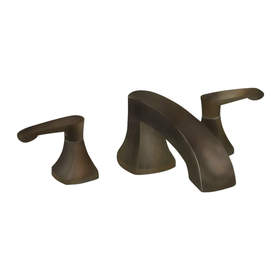
COPELAND
DECK-MOUNT BATH FILLER
Thank you for selecting American-Standard...the benchmark
of fine quality for over 100 years.
To ensure that your installation proceeds smoothly--please
read these instructions carefully before you begin.
Recommended Tools
Flat Blade Screwdriver
*Wrench
Adjustable Wrench
Channel Locks
*Supplied with Fitting
1
SPOUT ASSEMBLY
Turn off hot and cold water
CAUTION
supplies before beginning.
Install RING WASHER (1) into SPOUT recess. Check that O-RING (2)
on end of SPOUT SHANK (3) is in place. Insert SPOUT SHANK (3)
through center hole on mounting surface.
Assemble RUBBER WASHER (4) and BRASS WASHER (5) and
LOCKNUT (6) onto SPOUT SHANK (3). Align SPOUT ASSEMBLY
and from underside of ledge secure SPOUT ASSEMBLY into
position with LOCKNUT (6).
4
5
6
Installation
Instructions
ROUGHING-IN DIMENSIONS
9-3/8"
MOUNTING
*Hex key
SPOUT
ASSEMBLY
SPOUT RECESS
1
2
3
MOUNTING
SURFACE
7005.900
7005.901
4-1/8"
2"
SURFACE
1-1/8 DIA.
7"
3/4-14 MALE
N.P .T. INLETS
1-1/16 DIA.
2
PREPARE TUBE AND TEE ASSEMBLY
Prepare TUBE and TEE ASSEMBLY (1) to fit center to center
VALVE (2) location (between 6-1/2" and 12"). If necessary,
cut and/or bend TUBING carefully. Make sure tube bend is
close to the TEE (1) so that it will not effect the compression
joint at the VALVE CONNECTION.
Remove COUPLING NUT (3) and FERRULE (4) from each
VALVE (2) and slide onto TUBING (5).
VALVE inlet is 3/4-inch NPT male.
NOTE
Certified to comply with ANSI A112.18.1M
ADJ. 6-1/2 TO 12
2-3/4"
2-1/4"
1-1/4
MAX.
3
(C)
(H)
12 MAX
4
3
ADJ. 6-1/2 TO 12
M 9 6 8 6 3 8 R E V. 1. 1
8-3/16
2-1/16
DIA.
1-1/2 MAX.
1-3/16 DIA.
1
5
3
4
MOUNTING
SURFACE
2
Advertisement

Related Manuals for American Standard COPELAND 7005.900


Summary of Contents for American Standard COPELAND 7005.900
- Page 1 Installation Instructions COPELAND 7005.900 DECK-MOUNT BATH FILLER 7005.901 Thank you for selecting American-Standard...the benchmark of fine quality for over 100 years. To ensure that your installation proceeds smoothly--please read these instructions carefully before you begin. Certified to comply with ANSI A112.18.1M M 9 6 8 6 3 8 R E V.
- Page 2 VALVE ASSEMBLY MOUNTING SURFACE Install LOCKNUTS (1) and RUBBER WASHERS (2) onto valve shanks. Push TUBING (3) ends into VALVE (4) side outlets. Insert VALVES (4) into mounting holes from underside of ledge. Press TEE (5) onto SPOUT SHANK (6) making certain that the O-RING (7) is properly seated on SHANK (6).
- Page 3 HANDSHOWER INSTALLATION (FOR MODEL 7005.901 ONLY) Drop SPRAY ESCUTCHEON (1) through the fourth hole of the tub ledge (12" max from SPOUT center) with SPRAY ESCUTCHEON (1) directed towards tub center. Be sure RUBBER RING (2) is properly seated in ESCUTCHEON (1). Install RUBBER WASHER (3) and LOCKNUT (4) from underside of ledge.