Table of Contents
Advertisement
Advertisement
Table of Contents

Related Manuals for Supermicro SAS836TQ


Summary of Contents for Supermicro SAS836TQ
- Page 1 SAS 836TQ SAS 836TQ Backplane USER'S GUIDE Rev. 1.0...
-
Page 2: Table Of Contents
Table of Contents Safety Information and Technical Specifications ......1-3 1. Safety Guidelines ..................1-3 2. Introduction to the SAS836TQ Backplane ........... 1-4 3. Backplane Connectors and Jumpers ............1-5 A. Front Connectors ................1-8 A-1. Front Connector Locations .............. 1-5 A-2. -
Page 3: Safety Information And Technical Specifications
• Disconnect the power cable before installing or removing any cable from the SAS836TQ Backplane. • Make sure that the SAS836TQ Backplane is securely and properly installed on the motherboard to prevent damage to the system due to power shortage. -
Page 4: Introduction To The Sas836Tq Backplane
SES-2 backplane that offers the most advanced functionality provided by the Serial Attached/Serial Link Industry in a slim package. With the built-in AMI MG 9072 chip, the SAS836TQ Backplane allows the user to configure RAID 0, RAID 1 and RAID 5, maximizing data storage capability and data transferring reliability. Additionally, the... -
Page 5: Backplane Connectors And Jumpers
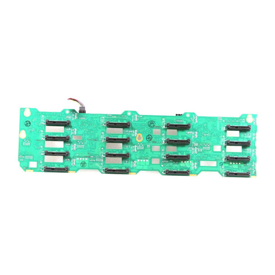
Safety Information and Technical Specifications 3. Backplane Connectors and Jumpers A. Front Connectors A-1 Front Connector Locations Front View JP82 JP78 JP106 JP105 JP69 9072 9072 SAS 836TQ JP52 JP96 JP95 JP37 JP65 JP77 JP68 JP66 JP48 JP13 JP75 JP46 JP10 JP61 JP64... -
Page 6: A-3. Front Panel Connector Pin Definitions
SAS836TQ Backplane User’s Guide A-3. Front Panel Connector Pin Definitions 1. Backplane Main Power Connectors (JP10, JP13, JP46, JP48) Pin Defini- tions 12V 4-pin Power Con- You must use the 4-pin power nector Pin Definitions connectors to provide adequate Pins Definition... - Page 7 Safety Information and Technical Specifications 6.a. Activity LED Header (Act-In1: #0-#7): JP26 Pin Definitions JP26 Act-In#1:JP26 (SAS#0-7) SAS Activity LED The Activity LED Header, located at JP26 on the front panel, transmits signals to indicate Pin# Pin# the activity status of each SAS slot from Slot0 Act In#0 Act In#4 Act In#0...
-
Page 8: Front Jumpers
SAS836TQ Backplane User’s Guide B. Front Jumpers B-1 Front Jumper Locations JP93 JP87 JP91 JP85 JP90 9072 JP89 JP83 JP84 9072 JP103 JP101 JP86 JP92 JP104 JP102 JP88 JP94 SAS 836TQ JP100 JP98 JP99 JP97 JP74 JP67 JP65 JP76 JP61... -
Page 9: B-3. Front Panel Led Locations
Safety Information and Technical Specifications B-3 Front Panel LED Locations SAS 836TQ... -
Page 10: Rear Connectors And Led Indicators
SAS836TQ Backplane User’s Guide C. Rear Connectors and LED Indicators C-1 Rear Connector/LED Locations Rear View SAS#3 SAS#11 SAS#15 SAS#7 SAS#10 SAS#2 SAS#6 SAS#14 SAS#1 SAS#9 SAS#5 SAS#13 SAS#4 SAS#12 SAS#0 SAS#8 C-2 Rear Connectors J1 SAS#0 J9 SAS#4 SAS#8...
Need help?
Do you have a question about the SAS836TQ and is the answer not in the manual?
Questions and answers