Table of Contents
Advertisement
Quick Links
Advertisement
Table of Contents

Subscribe to Our Youtube Channel
Related Manuals for Supermicro SuperBlade SBI-4119MG-X


Summary of Contents for Supermicro SuperBlade SBI-4119MG-X
- Page 1 SuperBlade ® SBI-4119MG-X USER’S MANUAL Revision 1.0...
- Page 2 State of California, USA. The State of California, County of Santa Clara shall be the exclusive venue for the resolution of any such disputes. Supermicro's total liability for all claims will not exceed the price paid for the hardware product.
-
Page 3: About This Manual
About this Manual This manual is written for professional system integrators and PC technicians. It provides information for the installation and use of the SuperBlade SBI-4119MG-X. Installation and maintenance should be performed by experienced technicians only. Please refer to the SBI-4119MG-X server specifications page on our website for updates on supported memory, processors and operating systems (http://www.supermicro.com). -
Page 4: Table Of Contents
Preface Contents Chapter 1 Introduction 1.1 Overview ..........................8 1.2 Product Checklist of Typical Components ................8 1.3 Blade Module Features ......................9 Processors ..........................9 Memory ..........................9 Storage ..........................10 RAID ..........................10 Enclosure Requirements ....................10 Density ..........................10 Chapter 2 Setup and Installation 2.1 Overview ..........................11 2.2 Installing Blade Modules ....................11 Powering Up a Blade Unit....................11 Powering Down a Blade Unit ....................11... - Page 5 SuperBlade SBI-4119MG-X User's Manual Chapter 3 Blade Module Features 3.1 Control Panel ........................24 Power Button ........................24 3.2 Motherboard ........................25 CMOS Clear ........................27 Jumper Settings ........................27 3.3 Blade Unit Components .....................28 Memory Support ........................29 M.2 NVMe Storage Module ....................29 Chapter 4 BIOS 4.1 Introduction .........................30...
- Page 6 Preface TLS Auth Configuration Sub-menu ...................47 Ram Disk Configuration Sub-menu ..................48 iSCSI Configuration Sub-menu ..................48 4.6 Event Logs Setup .......................50 4.7 IPMI Setup ..........................52 4.8 Security Setup ........................54 4.9 Boot Setup ..........................57 4.10 Save & Exit ........................59 Appendix A Updating BIOS Using KVM Console Appendix B Standardized Warning Statements for AC Systems B.1 About Standardized Warning Statements ................68...
- Page 7 SuperBlade SBI-4119MG-X User's Manual Contacting Supermicro Headquarters Address: Super Micro Computer, Inc. 980 Rock Ave. San Jose, CA 95131 U.S.A. Tel: +1 (408) 503-8000 Fax: +1 (408) 503-8008 Email: marketing@supermicro.com (General Information) support@supermicro.com (Technical Support) Website: www.supermicro.com Europe Address: Super Micro Computer B.V.
-
Page 8: Chapter 1 Introduction
If you have any questions, please contact our support team at: support@supermicro.com A complete list of safety warnings is provided on the Supermicro website at http://www.supermicro.com/about/policies/safety_information.cfm. 1.2 Product Checklist of Typical Components Your blade module ships with its B11SCG-CTF mainboard already installed in its chassis. -
Page 9: Blade Module Features
The SBI-4119MG-X SuperBlade module supports a single Intel Xeon E-2100, Socket H4 (LGA 1151) series processor. Refer to the Supermicro website for a complete listing of supported processors (http://www. supermicro.com/products/superblade). Please note that you will need to check the detailed specifications of a particular blade module for a list of the CPUs it supports. -
Page 10: Storage
SuperBlade SBI-4119MG-X User's Manual Please refer to the Supermicro website for a list of supported memory (www.supermicro.com/ products/superblade). The detailed specifications for a blade module will contain a link to a list of recommended memory sizes and manufacturers. Details on installation of memory modules into the SBI-4119MG-X SuperBlade module are found in Chapter 2: "Setup and Installation". -
Page 11: Chapter 2 Setup And Installation
Chapter 2: Server Installation Chapter 2 Setup and Installation 2.1 Overview This chapter covers the setup and installation of the blade module and its components. Please refer to Appendix B, Standardized Warning Statements for AC Systems before installing the system or components in this chapter. 2.2 Installing Blade Modules Up to 20 SBI-4119MG-X SuperBlade modules may be installed into a single blade enclosure. -
Page 12: Installing A Blade Unit Into The Enclosure
SuperBlade SBI-4119MG-X User's Manual 2. Squeeze the handle to depress the red section then pull out the blade unit from the enclosure using the handle. Note: Blade Modules can be Hot-Plugged from the enclosure. Installing a Blade Unit into the Enclosure Installing a Blade Unit into the Enclosure 1. -
Page 13: Motherboard Components
CPU socket and none of the socket pins are bent. If they are, contact your retailer. • Refer to the Supermicro website for updates on CPU support. Installing the LGA 1151 Processor 1. Press the load lever down to release the load plate from its locking position. - Page 14 SuperBlade SBI-4119MG-X User's Manual 2. Gently lift the load lever to open the load plate. Remove the plastic protective cover. Do not touch the CPU socket contacts. 3. Locate the triangle on the CPU and CPU socket, which indicates the location of Pin 1.
- Page 15 Chapter 2: Server Installation 5. Close the load plate, then gently push down the load lever into its locking position. CPU properly installed Load lever locked into place Note: You can only install the CPU in one direction. Make sure it is properly inserted into the socket before closing the load plate.
-
Page 16: Installing A Passive Cpu Heatsink
SuperBlade SBI-4119MG-X User's Manual Installing a Passive CPU Heatsink 1. Do not apply any thermal grease to the heatsink or the CPU die -- the required amount has already been applied. 2. Place the heatsink on top of the CPU so that the four mounting holes are aligned with those on the motherboard and the heatsink bracket underneath. -
Page 17: Removing The Cpu And The Heatsink
Chapter 2: Server Installation Removing the CPU and the Heatsink Warning: We do not recommend that the CPU or the heatsink be removed. However, if you do need to uninstall the CPU or the heatsink, please follow the instructions below to uninstall the heatsink or the CPU without damaging the CPU or the motherboard. -
Page 18: Memory Installation
64GB 32GB 32GB 32GB 32GB 128GB Check the Supermicro website for possible updates to memory support. Memory Population Guidelines • All DIMMs must be DDR4. • Balance memory. Using unbalanced memory topology, such as populating two DIMMs in one channel while populating one DIMM in another channel, reduces performance. It is not recommended for Supermicro systems. -
Page 19: Memory Population Sequence
Chapter 2: Server Installation Memory Population Sequence Blue slots versus black slots: Install the first DIMM in the blue memory slot, which is the first of a memory channel. Then, if using two DIMMs per channel, install the second DIMM in the black slot. -
Page 20: Installing Memory
SuperBlade SBI-4119MG-X User's Manual Installing Memory ESD Precautions Electrostatic Discharge (ESD) can damage electronic com ponents including memory modules. To avoid damaging DIMM modules, it is important to handle them carefully. The following measures are generally sufficient. • Use a grounded wrist strap designed to prevent static discharge. -
Page 21: Nvme Installation
Windows OS and blades with Linux OS can both occupy and operate within the same blade enclosure. Refer to the SuperMicro website for a complete list of supported operating systems. There are several methods of installing an OS to the blade modules. -
Page 22: Management Software
SuperBlade SBI-4119MG-X User's Manual Refer to the manuals on your SuperBlade CD-ROM for further details on the Virtual Media (CD-ROM or Drive Redirection) sections of these two utility programs. 2.7 Management Software System management may be performed with either of three software packages: IPMIview, IPMItool or a Web-based Management Utility. -
Page 23: Chapter 3 Blade Module Features
SuperBlade SBI-4119MG-X User's Manual Chapter 3 Blade Module Features This chapter describes the SBI-4119MG-X blade modules. Installation and maintenance should be performed by experienced technicians only. See Figure 3-1 for a front view of the blade units and the table below for their features. -
Page 24: Control Panel
Chapter 3: Maintenance and Component Installation 3.1 Control Panel Each blade has a similar control panel (Figure 3-2) with power on/off button, a KVM connector, a KVM button and four LEDs on the top front of the unit. The numbers mentioned in Figure 3-2 are described in the table below. -
Page 25: Motherboard
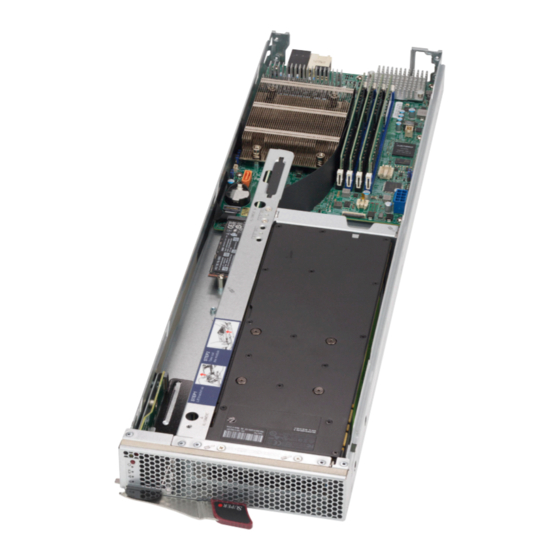
SuperBlade SBI-4119MG-X User's Manual 3.2 Motherboard The motherboard of the SBI-4119MG-X blade unit is a proprietary design, which is based on the Intel C246 chipset. See Figure 3-5 for a block diagram of this chipset. See Figure 3-6 and Figure 3-7 for exploded view diagrams of the blade unit. - Page 26 Chapter 3: Maintenance and Component Installation SBI-4119MG-X Module Layout Item Description CPU installed M.2 NVMe storage module DIMM slots (four) Power and Logic connectors to backplane PCI-E Module SATA Port 9-pin TPM Connector SUPERMICR B11SCG-ZTF/CTF REV 1.00 SYSTEM BLOCK DIAGRAM SVID IMVP8 IMVP8...
-
Page 27: Cmos Clear
SuperBlade SBI-4119MG-X User's Manual CMOS Clear JBT1 is used to clear CMOS and will also clear any passwords. This consists of two contact pads located near the BIOS chip. Clearing CMOS 1. First power down the blade and remove it from the enclosure. -
Page 28: Blade Unit Components
Chapter 3: Maintenance and Component Installation 3.3 Blade Unit Components Figure 3-6 Exploded View of the SBI-4119MG-X Blade Module Figure 3-7. Exploded View of the SBI-4119MG-X Blade Module Main Components of the SBI-4119MG-X Blade Modules Item Description Blade Module Cover CPU and Heatsink DIMM slots (4) Air Shroud... -
Page 29: Memory Support
SuperBlade SBI-4119MG-X User's Manual Memory Support The SBI-4119MG-X SuperBlade modules support up to 128 GB ECC UDIMM of DDR4 2666/2400/2133 MHz speed, 32GB, 16GB, 8GB, 4GB size SDRAM memory in four 288-pin DIMM sockets per node. See Section 2-4: Memory Installation for further details on motherboard memory installation. -
Page 30: Chapter 4 Bios
SuperBlade SBI-4119MG-X User's Manual Chapter 4 BIOS 4.1 Introduction This chapter describes the BIOS for Intel SuperBlade modules. The Blade modules use a 32 Mb SPI Flash EEPROM with AMI® BIOS that is stored in a flash chip. This BIOS can be easily upgraded using a floppy disk-based program. -
Page 31: Bios Updates
BIOS if you are not experiencing problems with a blade module. Updated BIOS files are located on our website (www.supermicro.com/products/superblade/). Please check the current BIOS revision and make sure it is newer than your current BIOS before downloading. -
Page 32: Main Bios Setup
SuperBlade SBI-4119MG-X User's Manual 4.4 Main BIOS Setup Figure 4-1. Main BIOS Setup Screen All Main Setup options are described in this section. Use the Up/Down arrow keys to move among the different settings in each menu. Use the Left/Right arrow keys to change the options for each setting. -
Page 33: Advanced Settings Menu
Chapter 4: BIOS BIOS Information BIOS static display information including the motherboard number, SMC version, SMC Build Date and Total Memory is also shown on the screen. 4.5 Advanced Settings Menu Figure 4-2. Advanced BIOS Setup Screen Choose Advanced from the BIOS Setup Utility main menu with the arrow keys to display the Advanced Setup menu. -
Page 34: Cpu Configuration Sub-Menu
SuperBlade SBI-4119MG-X User's Manual Option ROM Messages Use this setting to set the display mode for Option ROM to either Force BIOS or Keep Current. Bootup NUM-Lock State This setting selects the Power-On state for Numlock. Options include On or Off. - Page 35 Chapter 4: BIOS Adjacent Cache Line Prefetch This setting allows you to Enable or Disable the Adjacent Cache Line Prefetch. Intel (VMX) Virtualization Technology When enabled, a VMM can utilize the additional hardware capabilities provide by Vanderpool Technology. Option include Enabled and Disabled. Active Processor Cores This sets the number of cores to enable in each processor package.
- Page 36 SuperBlade SBI-4119MG-X User's Manual C States Use this setting to Enable/Disable CPU Power Management. Allows CPU to go to C states when it's not 100% utilized. Enhanced C-states Use this setting to Enable/Disable C1E. When enabled, the CPU will switch to minimum speed when all cores enter C-state.
-
Page 37: Chipset Configuration Sub-Menu
Chapter 4: BIOS Chipset Configuration Sub-menu System Agent (SA) Configuration Memory Configuration This sub-menu displays Memory Configuration settings. Maximum Memory Frequesncy This setting sets the Maximum Memory Frequency Selections in Mhz. Valid values should match the refclk, i.e. divide by 133 or 100. Options include Auto and number values from 1067 to 6000. - Page 38 SuperBlade SBI-4119MG-X User's Manual PEG Port Configuration Use this sub-menu to set PEG Port options for each PEG port. Enable Root Port Use this setting to configure the Root Port. Options include Disabled, Enabled or Auto. Max Link Speed Use this setting to configure PEG max speed. Options include Auto, Gen1, Gen2 or Gen3.
- Page 39 Chapter 4: BIOS Software Guard Extensions Use this setting to configure Software Guard Extensions (SGX). Options include Disabled, Enabled and Software Controlled. Select Owner EPOCH Input Type Use this setting to select the Owner EPOCH input type. There are three Owner EPOCH modes (each EPOCH is 64-bit): No Change in Owner EPOCHs, Change to New Random Owner EPOCHs and Manual User Defined Owner EPOCHs.
-
Page 40: Superio Device Configuration Sub-Menu
SuperBlade SBI-4119MG-X User's Manual M.2-H_1 Substates Use this setting to configure PCI Express L1 Substates settings. Options include Disabled, L1.1 and L1.1 & L1.2. M.2-H_1 PCIe Speed Use this setting to configure PCIe speed. Options include Auto, Gen1, Gen2 and Gen3. - Page 41 Chapter 4: BIOS Console Redirection Settings This feature allows the user to specify how the host computer will exchange data with the client computer, which is the remote computer used by the user. Terminal Type This feature allows the user to select the target terminal emulation type for Console Redirection.
-
Page 42: Legacy Console Redirection Sub-Menu
SuperBlade SBI-4119MG-X User's Manual Recorder Mode Select Enabled to capture the data displayed on a terminal and send it as text messages to a remote server. The options are Disabled and Enabled. Resolution 100x31 Select Enabled for extended-terminal resolution support. The options are Disabled and Enabled. -
Page 43: Serial Port For Out-Of-Band Management/Windows Emergency Management Services (Ems)
Chapter 4: BIOS Serial Port for Out-of-Band Management/Windows Emergency Management Services (EMS) Console Redirection (for EMS) Select Enabled to use a COM Port selected by the user for Console Redirection. The options are Enabled and Disabled. Console Redirection Settings (for EMS) This feature allows the user to specify how the host computer will exchange data with the client computer, which is the remote computer used by the user. -
Page 44: Sata And Rste Configuration Sub-Menu
SuperBlade SBI-4119MG-X User's Manual SATA and RSTe Configuration Sub-menu SATA Controller This setting allows you to Enable or Disable the SATA device. SATA Mode Selections Use this setting to select the SATA mode you desire. Options include AHCI and RAID. -
Page 45: Usb Configuration Sub-Menu
Chapter 4: BIOS USB Configuration Sub-menu Legacy USB Support This setting enables Legacy USB support. Options include Enabled, Disabled and Auto. The Auto option disables legacy support if no USB devices are connected. The disable option will keep USB devices available only for EFI applications. XHCI Hand-off This setting is a workaround for OSes without XHCI hand-off support. -
Page 46: Pci Devices Option Rom Setting
SuperBlade SBI-4119MG-X User's Manual SERR# Generation This setting Enables/Disables PCI Device to generate SERR#. Above 4G Decoding Select Enabled to decode a 64-bit PCI device in the space above 4G Address. The options are Enabled and Disabled. SR-IOV Support If the system has SR-10V capable PCIe device, this option Enables or Disables single root I/O virtualization support. -
Page 47: Trusted Computing Sub-Menu
Chapter 4: BIOS Ipv4 HTTP Support This setting allows you to Enable or Disable Ipv4 HTTP support for your system. If disabled, the boot option for Ipv4 HTTP Support will not be created. Ipv6 PXE Support This setting allows you to Enable or Disable Ipv6 PXE Support for your system. If disabled, the boot option for Ipv4 PXE Support will not be created. -
Page 48: Ram Disk Configuration Sub-Menu
SuperBlade SBI-4119MG-X User's Manual uDiscard Changes and Exit Use this link to discard changes and exit. Delete Certification Sub-menu Use this link to delete a certification previously enrolled. Ram Disk Configuration Sub-menu Disk Memory Type: This setting specifies the type of memory to use from the available memory pool in the system to create a disk. - Page 49 Chapter 4: BIOS Change Attempt Order Use this link to delete an attempt.
-
Page 50: Event Logs Setup
SuperBlade SBI-4119MG-X User's Manual 4.6 Event Logs Setup Figure 4-3. Event Logs Setup Screen Change SMBIOS Event Log Settings This sub-menu allows you to change the SMBIOS Event Log configuration settings. SMBIOS Event Log Change this setting to enable or disable all features of the SMBIOS Event Logging during system boot. - Page 51 Chapter 4: BIOS Log System Boot Event This option toggles the System Boot Event logging to enabled or disabled. The options are Disabled and Enabled. MECI The Multiple Event Count Increment (MECI) counter counts the number of occurrences that a duplicate event must happen before the MECI counter is incremented. This is a numeric value.
-
Page 52: Ipmi Setup
SuperBlade SBI-4119MG-X User's Manual 4.7 IPMI Setup Figure 4-4. IPMI Setup Screen IPMI Information IPMI Firmware Revision and IPMI Status information are statically displayed at the top of this menu. System Event Log Selecting this sub-menu displays settings for changing the SEL Event Log configuration. Note: all values changed here do not take effect until the system is restarted. - Page 53 Chapter 4: BIOS When SEL is Full Use this setting to choose options for reactions to a full SEL. Options include Do Nothing and Erase Immediately. Log EFI Status Codes Use this setting to enable or disable logging of EFI status codes, log only Disabled, Error Code, only Progress Code or Both.
-
Page 54: Security Setup
SuperBlade SBI-4119MG-X User's Manual 4.8 Security Setup Figure 4-5. Security Setup Screen Administrator Password This allows you to create an administrator password for the system. User Password This allows you to create user password for the system. Password Check Use this setting to specify when to do a password check. Options include checking the password while invoking Setup, or Always when invoking setup as well as on each boot. - Page 55 Chapter 4: BIOS Set User Password Use this setting to set an HDD User Password. Note: It is advisable to power the cycle system after setting a hard disk password. Discard or save changes in setup do not have any impact on the HDD when the password is set or removed.
- Page 56 SuperBlade SBI-4119MG-X User's Manual uEnroll EFI Image When selected, this setting allows the image to run in Secure Boot Mode. This enrolls the SHA256 Hash certificate of a PE image into the Authorized Signature Database (db). uRestore DB defaults Use this setting to restore the DB variable to factory defaults. Options include Yes or No.
-
Page 57: Boot Setup
Chapter 4: BIOS 4.9 Boot Setup Figure 4-6. Boot Setup Screen Fast Boot Enables or Disables boot wih an initialization of a minimal set of devices required to launch the active boot option. This has no effect for BBS boot devices. Options include Disable Link or Enabled. - Page 58 SuperBlade SBI-4119MG-X User's Manual Delete Boot Option This sub-menu allows you to remove an EFI boot option form the boot order. Delete Driver Option This sub-menu allows you to remove an EFI driver option form the boot order. UEFI Application Boot Priorities Use this submenu to specify the boot device priority sequence from the available UEFI Hard Disk Drives in the system.
-
Page 59: Save & Exit
Chapter 4: BIOS 4.10 Save & Exit Figure 4-7. Save & Exit Setup Screen Discard Changes and Exit Highlight this item and hit <Enter> to exit the BIOS Setup utility without saving any changes you may have made. Any changes you have made to the BIOS Setup will not take effect upon system bootup. - Page 60 SuperBlade SBI-4119MG-X User's Manual Restore Defaults Highlight this item and hit <Enter> to load the default settings for all items in the BIOS Setup. These are the safest settings to use and are designed for maximum system performance, but may not work best for all computer applications.
-
Page 61: Appendix A Updating Bios Using Kvm Console
Appendix A: BIOS Error Codes Appendix A Updating BIOS Using KVM Console Use the following procedure to update a module BIOS using the KVM console software. Updating the BIOS Using the KVM Console 1. Click on the graphic in the System -> System Information screen to launch the KVM Console window as shown in Figure A-1. - Page 62 SuperBlade SBI-4119MG-X User's Manual 2. In the KVM Console window, click on the Virtual Storage menu option from the Virtual Media menu (Figure A-3). The Virtual Storage window will be displayed (Figure A-4). Figure A-3. KVM Console Window Figure A-4. Virtual Storage Window...
- Page 63 Appendix A: BIOS Error Codes 3. Under the Device 1 tab of the Virtual Storage window, select ISO File from the Logical Drive Type menu if you wish to mount an ISO file (Figure A-5). Figure A-5. Selecting ISO File to Mount an ISO File 4.
- Page 64 SuperBlade SBI-4119MG-X User's Manual 5. After you have selected the ISO file, press the Plug In button, then the OK button to exit the Virtual Storage window (Figure A-7). Skip ahead to step 8. Figure A-7. Pressing the Plug in and OK Buttons for an ISO File 6.
- Page 65 Appendix A: BIOS Error Codes 7. After you have selected the USB flash drive file, press the Plug In button, then the OK button to exit the Virtual Storage window (Figure A-9). Figure A-9. Pressing the Plug In and OK Buttons for an USB Flash Drive File 8.
- Page 66 SuperBlade SBI-4119MG-X User's Manual When the system powers up, press your keyboard’s F11 key in order to boot into the Invoke Bootable Devices List. From this list, select the ATEN Virtual CDROM YS0J command. Your MicroBlade will now boot up into mounting the ISO file which contains the new BIOS file and flash utility (Figure A-11).
- Page 67 Appendix A: BIOS Error Codes 9. Close the KVM Console window, or go to the Virtual Storage window (see step 2) and click on Plug Out, this will remove mounting of the ISO file (Figure A-12). Figure A-12. Clicking Plug Out in the Virtual Storage Window...
-
Page 68: Appendix B Standardized Warning Statements For Ac Systems
Supermicro's Technical Support department for assistance. Only certified technicians should attempt to install or configure components. Read this appendix in its entirety before installing or configuring components in the Supermicro chassis. These warnings may also be found on our website at http://www.supermicro.com/about/... - Page 69 Appendix B: Standardized Warning Statements Warnung WICHTIGE SICHERHEITSHINWEISE Dieses Warnsymbol bedeutet Gefahr. Sie befinden sich in einer Situation, die zu Verletzungen führen kann. Machen Sie sich vor der Arbeit mit Geräten mit den Gefahren elektrischer Schaltungen und den üblichen Verfahren zur Vorbeugung vor Unfällen vertraut. Suchen Sie mit der am Ende jeder Warnung angegebenen Anweisungsnummer nach der jeweiligen Übersetzung in den übersetzten Sicherheitshinweisen, die zusammen mit diesem Gerät ausgeliefert wurden.
- Page 70 SuperBlade SBI-4119MG-X User's Manual . ٌ ا ك ً ف حالة و ٌ يك أى تتسبب ف اصابة جسذ ة ٌ هذا الزهز ع ٌ خطز !تحذ ز قبل أى تعول عىل أي هعذات،يك عىل علن بالوخاطز ال ا ٌجوة عي الذوائز...
- Page 71 Appendix B: Standardized Warning Statements Warnung Vor dem Anschließen des Systems an die Stromquelle die Installationsanweisungen lesen. ¡Advertencia! Lea las instrucciones de instalación antes de conectar el sistema a la red de alimentación. Attention Avant de brancher le système sur la source d'alimentation, consulter les directives d'installation. .יש...
- Page 72 SuperBlade SBI-4119MG-X User's Manual Warnung Dieses Produkt ist darauf angewiesen, dass im Gebäude ein Kurzschluss- bzw. Überstromschutz installiert ist. Stellen Sie sicher, dass der Nennwert der Schutzvorrichtung nicht mehr als: 250 V, 20 A beträgt. ¡Advertencia! Este equipo utiliza el sistema de protección contra cortocircuitos (o sobrecorrientes) del edificio.
- Page 73 Appendix B: Standardized Warning Statements Power Disconnection Warning Warning! The system must be disconnected from all sources of power and the power cord removed from the power supply module(s) before accessing the chassis interior to install or remove system components. 電源切断の警告...
- Page 74 SuperBlade SBI-4119MG-X User's Manual يجب فصم اننظاو من جميع مصادر انطاقت وإ ز انت سهك انكهرباء من وحدة امداد انطاقت قبم انىصىل إىن امنناطق انداخهيت نههيكم نتثبيج أو إ ز انت مكىناث الجهاز 경고! 시스템에 부품들을 장착하거나 제거하기 위해서는 섀시 내부에 접근하기 전에 반드시 전원...
- Page 75 Appendix B: Standardized Warning Statements Attention Il est vivement recommandé de confier l'installation, le remplacement et la maintenance de ces équipements à des personnels qualifiés et expérimentés. !אזהרה .צוות מוסמך בלבד רשאי להתקין, להחליף את הציוד או לתת שירות עבור הציוד واملدربيه...
- Page 76 SuperBlade SBI-4119MG-X User's Manual Warnung Diese Einheit ist zur Installation in Bereichen mit beschränktem Zutritt vorgesehen. Der Zutritt zu derartigen Bereichen ist nur mit einem Spezialwerkzeug, Schloss und Schlüssel oder einer sonstigen Sicherheitsvorkehrung möglich. ¡Advertencia! Esta unidad ha sido diseñada para instalación en áreas de acceso restringido. Sólo puede obtenerse acceso a una de estas áreas mediante la utilización de una herramienta especial,...
- Page 77 Appendix B: Standardized Warning Statements Battery Handling Warning! There is the danger of explosion if the battery is replaced incorrectly. Replace the battery only with the same or equivalent type recommended by the manufacturer. Dispose of used batteries according to the manufacturer's instructions 電池の取り扱い...
- Page 78 SuperBlade SBI-4119MG-X User's Manual هناك خطر من انفجار يف حالة اسحبذال البطارية بطريقة غري صحيحة فعليل اسحبذال البطارية فقط بنفس النىع أو ما يعادلها مام أوصث به الرشمة املصنعة جخلص من البطاريات املسحعملة وفقا لحعليامت الرشمة الصانعة 경고! 배터리가 올바르게 교체되지 않으면 폭발의 위험이 있습니다. 기존 배터리와 동일하거나 제...
- Page 79 Appendix B: Standardized Warning Statements ¡Advertencia! Puede que esta unidad tenga más de una conexión para fuentes de alimentación. Para cortar por completo el suministro de energía, deben desconectarse todas las conexiones. Attention Cette unité peut avoir plus d'une connexion d'alimentation. Pour supprimer toute tension et tout courant électrique de l'unité, toutes les connexions d'alimentation doivent être débranchées.
- Page 80 SuperBlade SBI-4119MG-X User's Manual Backplane Voltage Warning! Hazardous voltage or energy is present on the backplane when the system is operating. Use caution when servicing. バックプレーンの電圧 システムの稼働中は危険な電圧または電力が、 バックプレーン上にかかっています。 修理する際には注意く ださい。 警告 当系统正在进行时,背板上有很危险的电压或能量,进行维修时务必小心。 警告 當系統正在進行時,背板上有危險的電壓或能量,進行維修時務必小心。 Warnung Wenn das System in Betrieb ist, treten auf der Rückwandplatine gefährliche Spannungen oder Energien auf.
- Page 81 Appendix B: Standardized Warning Statements هناك خطز مه التيار الكهزبايئ أوالطاقة املىجىدة عىل اللىحة عندما يكىن النظام يعمل كه حذ ر ا عند خدمة هذا الجهاس 경고! 시스템이 동작 중일 때 후면판 (Backplane)에는 위험한 전압이나 에너지가 발생 합니다. 서비스 작업 시 주의하십시오. Waarschuwing Een gevaarlijke spanning of energie is aanwezig op de backplane wanneer het systeem in gebruik is.
- Page 82 SuperBlade SBI-4119MG-X User's Manual תיאום חוקי החשמל הארצי !אזהרה .התקנת הציוד חייבת להיות תואמת לחוקי החשמל המקומיים והארציים تركيب املعدات الكهربائية يجب أن ميتثل للقىاويه املحلية والىطىية املتعلقة بالكهرباء 경고! 현 지역 및 국가의 전기 규정에 따라 장비를 설치해야 합니다.
- Page 83 Appendix B: Standardized Warning Statements Attention La mise au rebut ou le recyclage de ce produit sont généralement soumis à des lois et/ou directives de respect de l'environnement. Renseignez-vous auprès de l'organisme compétent. סילוק המוצר !אזהרה .סילוק סופי של מוצר זה חייב להיות בהתאם להנחיות וחוקי המדינה التخلص...
- Page 84 SuperBlade SBI-4119MG-X User's Manual Warnung Gefährlich Bewegende Teile. Von den bewegenden Lüfterblätter fern halten. Die Lüfter drehen sich u. U. noch, wenn die Lüfterbaugruppe aus dem Chassis genommen wird. Halten Sie Finger, Schraubendreher und andere Gegenstände von den Öffnungen des Lüftergehäuses entfernt.
- Page 85 Verbindungskabeln, Stromkabeln und/oder Adapater, die Ihre örtlichen Sicherheitsstandards einhalten. Der Gebrauch von anderen Kabeln und Adapter können Fehlfunktionen oder Feuer verursachen. Die Richtlinien untersagen das Nutzen von UL oder CAS zertifizierten Kabeln (mit UL/CSA gekennzeichnet), an Geräten oder Produkten die nicht mit Supermicro gekennzeichnet sind.
- Page 86 حجم املوصل والقابس السليم. استخدام أي كابالت ومحوالت أخرى قد يتسبب يف عطل أو حريق. يحظر قانون السالمة لألجهزة الكهربائية واملعدات استخدام الكابالت املعتمدة من قبلUL أوCSA ( والتي تحمل عالمةUL/CSA) مع أي معدات أخرى غري املنتجات املعنية واملحددة من قبلSupermicro.
- Page 87 사항을 준수하여 제공되거나 지정된 연결 혹은 구매 케이블, 전원 케이블 및 AC 어댑터를 사용하십시오. 다른 케이블이나 어댑터를 사용하면 오작동이나 화재가 발생할 수 있습니다. 전기 용품 안전법은 UL 또는 CSA 인증 케이블 (코드에 UL / CSA가 표시된 케이블)을 Supermicro 가 지정한 제품 이외의 전기 장치에 사용하는 것을 금지합니다. Stroomkabel en AC-Adapter...
Need help?
Do you have a question about the SuperBlade SBI-4119MG-X and is the answer not in the manual?
Questions and answers