Table of Contents
Advertisement
Quick Links
Advertisement
Table of Contents

Related Manuals for Supermicro SuperBlade SBI-6419P-C3N


Summary of Contents for Supermicro SuperBlade SBI-6419P-C3N
- Page 1 SBI-6419P-C3N SuperBlade Module User’s Manual Revison 1.0...
- Page 2 This product, including software and documentation, is the property of Supermicro and/or its licensors, and is supplied only under a license. Any use or reproduction of this product is not allowed, except as expressly permitted by the terms of said license.
- Page 3 This manual is written for professional system integrators, Information Technology professionals, service personnel and technicians. It provides information for the ® installation and use of the Supermicro SuperBlade system’s SBI-6419P-C3N SuperBlade module. Installation and maintenance should be performed by experienced professionals only.
- Page 4 SBI-6419P-C3N SuperBlade Module User’s Manual...
-
Page 5: Table Of Contents
Processors ....................1-2 Memory ....................1-2 Storage ....................1-3 RAID ....................... 1-3 Enclosure Requirements................. 1-3 Density ....................1-3 1-4 Contacting Supermicro ..............1-4 Chapter 2 Standardized Warning Statements ..... 2-1 2-1 About Standardized Warning Statements ........2-1 Warning Definition................... 2-1 Installation Instructions ................ - Page 6 SBI-6419P-C3N SuperBlade Module User’s Manual Overview of the Processor Socket Assembly ......... 3-5 Overview of the Processor Heatsink Module (PHM)....... 3-6 Attaching the Processor to the Narrow Processor Clip to Create the Processor Package Assembly ..............3-7 Attaching the Processor Package Assembly to the Heatsink to Form the Processor Heatsink Module (PHM)............
- Page 7 Table of Contents 5-4 Main BIOS Setup ................5-3 5-5 Advanced Setup ................5-5 5-6 Event Logs Setup ................5-17 5-7 IPMI Setup ..................5-19 5-8 Security ..................... 5-21 5-9 Boot ....................5-23 5-10 Save & Exit ..................5-25 Appendix A Updating BIOS Using KVM Console ....A-1...
- Page 8 SBI-6419P-C3N SuperBlade Module User’s Manual Notes viii...
-
Page 9: Chapter 1 Introduction
• If you have any questions, please contact our support team at: support@supermicro.com Note: A complete list of safety warnings is provided on the Supermicro website at http://www.supermicro.com/about/policies/safety_information.cfm. Product Checklist of Typical Components Your blade module ships with its B11SPE-CPU-TF/25G mainboard already installed in its chassis. -
Page 10: Blade Module Features
Processors The SBI-6419P-C3N SuperBlade module supports a single Intel Xeon Scalable, Socket P LGA 3647 series processor. Refer to the Supermicro website for a complete listing of supported processors (http:// www.supermicro.com/products/superblade). Please note that you will need to check the detailed specifications of a particular blade module for a list of the CPUs it supports. -
Page 11: Storage
Chapter 1: Introduction Please refer to the Supermicro website for a list of supported memory (www.supermicro.com/products/superblade). The detailed specifications for a blade module will contain a link to a list of recommended memory sizes and manufacturers. Details on installation of memory modules into the SBI-6419P-C3N SuperBlade module are found in Chapter 3: "Setup and Installation"... -
Page 12: Contacting Supermicro
SBI-6419P-C3N SuperBlade Module User’s Manual Contacting Supermicro Headquarters Address: Supermicro Computer, Inc. 980 Rock Ave. San Jose, CA 95131 U.S.A. Tel: +1 (408) 503-8000 Fax: +1 (408) 503-8008 marketing@supermicro.com (General Information) Email: support@supermicro.com (Technical Support) website: www.supermicro.com Europe Address: Supermicro Computer B.V. -
Page 13: Chapter 2 Standardized Warning Statements
The following statements are industry standard warnings, provided to warn the user of situations which have the potential for bodily injury. Should you have questions or experience difficulty, contact Supermicro's Technical Support department for assistance. Only certified technicians should attempt to install or configure components. - Page 14 SBI-6419P-C3N SuperBlade Module User’s Manual Warnung WICHTIGE SICHERHEITSHINWEISE Dieses Warnsymbol bedeutet Gefahr. Sie befinden sich in einer Situation, die zu Verletzungen führen kann. Machen Sie sich vor der Arbeit mit Geräten mit den Gefahren elektrischer Schaltungen und den üblichen Verfahren zur Vorbeugung vor Unfällen vertraut.
-
Page 15: Installation Instructions
Chapter 2: Standardized Warning Statements 안전을 위한 주의사항 경고 ! 이 경고 기호는 위험이 있음을 알려 줍니다 . 작업자의 신체에 부상을 야기 할 수 있는 상태에 있게 됩니다 . 모든 장비에 대한 작업을 수행하기 전에 전기회로와 관련된 위험 요소들을 확인하시고 사전에 사고를 방지할 수 있도록 표준 작업절차를 준수해 주시기 바랍니다... -
Page 16: Circuit Breaker
SBI-6419P-C3N SuperBlade Module User’s Manual Attention Avant de brancher le système sur la source d'alimentation, consulter les directives d'installation. מתח את הוראות התקנה לפני חיבור המערכת למקור יש לקרוא ﻣﺼﺪر ﻟﻠﻄﺎﻗﺔ اﻟﻨﻈﺎم إﻟﻰ ﻗﺒﻞ ﺗﻮﺻﯿﻞ ﺘﺮﻛﯿﺐ اﻗﺮ إرﺷﺎدات اﻟ 시스템을 전원에 연결하기 전에 설치 안내를 읽어주십시오 . Waarschuwing Raadpleeg de installatie-instructies voordat u het systeem op de voedingsbron aansluit. -
Page 17: Power Disconnection Warning
Chapter 2: Standardized Warning Statements קצר חשמלי. יש לוודא כי המותקנת במבנים למניעת ה הגנ מוצר זה מסתמך על הוא לא יותר מ החשמלי המכשיר המגן מפני הקצר 250 V, 20 A ﻓﻲ اﻟﺘﻲ ﺗﻢ ﺗﺜﺒﯿﺘﮭﺎ ﻣﻦ اﻟﺪواﺋﺮاﻟﻘﺼﯿﺮة اﻟﺤﻤﺎﯾﺔ ﻣﻌﺪات ﯾﻌﺘﻤﺪ... -
Page 18: Equipment Installation
SBI-6419P-C3N SuperBlade Module User’s Manual ¡Advertencia! El sistema debe ser disconnected de todas las fuentes de energía y del cable eléctrico quitado de los módulos de fuente de alimentación antes de tener acceso el interior del chasis para instalar o para quitar componentes de sistema. Attention Le système doit être débranché... -
Page 19: Restricted Area
Chapter 2: Standardized Warning Statements Warnung Das Installieren, Ersetzen oder Bedienen dieser Ausrüstung sollte nur geschultem, qualifiziertem Personal gestattet werden. ¡Advertencia! Solamente el personal calificado debe instalar, reemplazar o utilizar este equipo. Attention Il est vivement recommandé de confier l'installation, le remplacement et la maintenance de ces équipements à... - Page 20 SBI-6419P-C3N SuperBlade Module User’s Manual Warnung Diese Einheit ist zur Installation in Bereichen mit beschränktem Zutritt vorgesehen. Der Zutritt zu derartigen Bereichen ist nur mit einem Spezialwerkzeug, Schloss und Schlüssel oder einer sonstigen Sicherheitsvorkehrung möglich. ¡Advertencia! Esta unidad ha sido diseñada para instalación en áreas de acceso restringido. Sólo puede obtenerse acceso a una de estas áreas mediante la utilización de una herramienta especial, cerradura con llave u otro medio de seguridad.
-
Page 21: Battery Handling
Chapter 2: Standardized Warning Statements Battery Handling Warning! There is the danger of explosion if the battery is replaced incorrectly. Replace the battery only with the same or equivalent type recommended by the manufacturer. Dispose of used batteries according to the manufacturer's instructions. 電池の取り扱い... -
Page 22: Redundant Power Supplies
SBI-6419P-C3N SuperBlade Module User’s Manual 경고 ! 배터리가 올바르게 교체되지 않으면 폭발의 위험이 있습니다 . 기존 배터리와 동일하거 나 제조사에서 권장하는 동등한 종류의 배터리로만 교체해야 합니다 . 제조사의 안내에 따라 사용된 배터리를 처리하여 주십시오 . Waarschuwing Er is ontploffingsgevaar indien de batterij verkeerd vervangen wordt. Vervang de batterij slechts met hetzelfde of een equivalent type die door de fabrikant aanbevolen wordt. -
Page 23: Backplane Voltage
Chapter 2: Standardized Warning Statements اﻣﺪاد اﻟﻄﺎﻗﺔ ﺑﻮﺣﺪات ﻋﺪة اﺗﺼﺎﻻت ﺠﮭﺎز اﻟ ﯾﻜﻮن ﻟﮭﺬا ﻗﺪ اﻟﻜﮭﺮﺑﺎء ﻋﻦ ﻮﺣﺪة اﻟ ﻟﻌﺰل ﻛﺎﻓﺔ اﻻﺗﺼﺎﻻت ﯾﺠﺐ إزاﻟﺔ 경고 ! 이 장치에는 한 개 이상의 전원 공급 단자가 연결되어 있을 수 있습니다 . 이 장치에 전 원을... -
Page 24: Comply With Local And National Electrical Codes
SBI-6419P-C3N SuperBlade Module User’s Manual اﻟﻠﻮﺣﺔ أواﻟﻄﺎﻗﺔ اﻟﻤﻮﺟﻮدة ﻋﻠﻰ اﻟﺘﯿﺎر اﻟﻜﮭﺮﺑﺎﺋﻲ ﻣﻦ ﺧﻄﺮ ھﻨﺎك ھﺬا اﻟﺠﮭﺎز ﺧﺪﻣﺔ ﻛﻦ ﺣﺬرا ﻋﻨﺪ ﯾﻌﻤﻞ اﻟﻨﻈﺎم ﻋﻨﺪﻣﺎ ﯾﻜﻮن 경고 ! 시스템이 동작 중일 때 후면판 (Backplane) 에는 위험한 전압이나 에너지가 발생 합니 다 . 서비스 작업 시 주의하십시오 . Waarschuwing Een gevaarlijke spanning of energie is aanwezig op de backplane wanneer het systeem in gebruik is. -
Page 25: Product Disposal
Chapter 2: Standardized Warning Statements 경고 ! 현 지역 및 국가의 전기 규정에 따라 장비를 설치해야 합니다 . Waarschuwing Bij installatie van de apparatuur moet worden voldaan aan de lokale en nationale elektriciteitsvoorschriften. Product Disposal Warning! Ultimate disposal of this product should be handled according to all national laws and regulations. -
Page 26: Hot Swap Fan Warning
SBI-6419P-C3N SuperBlade Module User’s Manual 경고 ! 이 제품은 해당 국가의 관련 법규 및 규정에 따라 폐기되어야 합니다 . Waarschuwing De uiteindelijke verwijdering van dit product dient te geschieden in overeenstemming met alle nationale wetten en reglementen. Hot Swap Fan Warning Warning! The fans might still be turning when you remove the fan assembly from the chassis. -
Page 27: Power Cable And Ac Adapter
Electrical Appliance and Material Safety Law prohibits the use of UL or CSA -certified cables (that have UL/CSA shown on the code) for any other electrical devices than products designated by Supermicro only. 電源コードと AC アダプター... - Page 28 Fehlfunktion oder ein Brand entstehen. Elektrische Geräte und Material Safety Law verbietet die Verwendung von UL-oder CSA-zertifizierte Kabel, UL oder CSA auf der Code für alle anderen elektrischen Geräte als Produkte von Supermicro nur bezeichnet gezeigt haben.
- Page 29 Het gebruik van andere kabels en adapters kan leiden tot een storing of een brand. Elektrisch apparaat en veiligheidsinformatiebladen wet verbiedt het gebruik van UL of CSA gecertificeerde kabels die UL of CSA die op de code voor andere elektrische apparaten dan de producten die door Supermicro alleen. 2-17...
- Page 30 SBI-6419P-C3N SuperBlade Module User’s Manual 2-18...
-
Page 31: Chapter 3 Setup And Installation
Chapter 3: Setup and Installation Chapter 3 Setup and Installation Overview This chapter covers the setup and installation of the blade module and its components. Installing Blade Modules Up to 14 SBI-6419P-C3N SuperBlade modules may be installed into a single blade enclosure. -
Page 32: Removing A Blade Unit From The Enclosure
SBI-6419P-C3N SuperBlade Module User’s Manual Removing a Blade Unit from the Enclosure Although the blade system may continue to run, individual blades should always be powered down before removing them from the enclosure. Removing a Blade Unit from the Enclosure 1. - Page 33 Chapter 3: Setup and Installation Figure 3-1. Inserting a Blade into the Enclosure...
-
Page 34: Processor Installation
CPU socket cap is in place and that none of the socket pins are bent; otherwise, contact your retailer immediately. 3. Refer to the Supermicro website for updates on CPU support. 4. Please follow the instructions given in the ESD Warning section on the first page of this chapter before handling, installing, or removing system components. -
Page 35: Overview Of The Processor Socket Assembly
Chapter 3: Setup and Installation Overview of the Processor Socket Assembly The processor socket assembly contains 1) the processor, 2) the narrow processor clip, 3) the dust cover, and 4) the CPU socket. 1. Processor 2. Narrow processor clip (the plastic processor package carrier used for the CPU) 3. -
Page 36: Overview Of The Processor Heatsink Module (Phm)
SBI-6419P-C3N SuperBlade Module User’s Manual Overview of the Processor Heatsink Module (PHM) The Processor Heatsink Module (PHM) contains 1) a heatsink, 2) a narrow processor clip, and 3) the processor. 1. Heatsink 2. Narrow Processor Clip 3. Processor Bottom View... -
Page 37: Attaching The Processor To The Narrow Processor Clip To Create The Processor Package Assembly
Chapter 3: Setup and Installation Attaching the Processor to the Narrow Processor Clip to Create the Processor Package Assembly To properly install the CPU into the narrow processor clip, please follow the steps below. 1. Locate pin 1 (notch A), which is the triangle located on the top of the narrow processor clip. -
Page 38: Attaching The Processor Package Assembly To The Heatsink To Form The Processor Heatsink Module (Phm)
SBI-6419P-C3N SuperBlade Module User’s Manual Attaching the Processor Package Assembly to the Heatsink to Form the Processor Heatsink Module (PHM) After you have made a processor package assembly by following the instructions on the previous page, please follow the steps below to mount the processor package assembly onto the heatsink to create the Processor Heatsink Module (PHM). - Page 39 Chapter 3: Setup and Installation Non-Fabric CPU and Processor Clip (Upside Down) Triangle on the CPU Triangle on the Processor Clip Heatsink (Upside Down) On Locations of (C, D), the notches snap onto the heat sink’s mounting holes On Locations (A, B), the notches Make sure Mounting snap onto the heatsink’s sides Notches snap into place...
-
Page 40: Preparing The Cpu Socket For Installation
SBI-6419P-C3N SuperBlade Module User’s Manual Preparing the CPU Socket for Installation This motherboard comes with the CPU socket pre-assembled in the factory. The CPU socket contains 1) a dust cover, 2) a socket bracket, 3) the CPU (P0) socket, and 4) a back plate. - Page 41 Chapter 3: Setup and Installation Installing the Processor Heatsink Module (PHM) Once you have assembled the processor heatsink module (PHM) by following the previous instructions, you are ready to install the processor heatsink module (PHM) into the CPU socket on the motherboard. To install the PHM into the CPU socket, follow the instructions below.
-
Page 42: Removing The Processor Heatsink Module (Phm) From The Motherboard
SBI-6419P-C3N SuperBlade Module User’s Manual Removing the Processor Heatsink Module (PHM) from the Motherboard Before removing the processor heatsink module (PHM), unplug power cord from the power outlet. 1. Using a T30 Torx-bit screwdriver, turn the screws on the PHM counterclockwise to loosen them from the socket, starting with screw marked #4 (in the sequence of 4, 3, 2, 1). -
Page 43: Onboard Battery Installation
The mainboard of each blade unit must be populated with DIMMs (Dual In-line Memory Modules) to provide system memory. The DIMMs should all be of the same size and speed and from the same Supermicro authorized manufacturer due to compatibility issues. See details below on supported memory and our website (www.supermicro.com/products/superblade... - Page 44 SBI-6419P-C3N SuperBlade Module User’s Manual Notes: 1. Be sure to use the memory modules of the same type and speed on the motherboard. Mixing of memory modules of different types and speeds is not allowed. 2. When installing memory modules, be sure to populate the first DIMM module on the blue memory slot, which is the first memory slot of a memory channel, and then populate the second DIMM in the black slot if 2DPC memory configuration is used.
-
Page 45: Dimm Population Requirements For The Processors
Chapter 3: Setup and Installation Table 3-2. DDR4 Memory Support (for 1 Slot per Channel Configuration) Speed (M/Ts); Voltage (V), Slots per Channel (SPC), and DIMMs per Channel (DPC) Ranks DIMM Capacity (GB) Per DIMM 1 slots per Channel Type and Data Width 1DPC... - Page 46 SBI-6419P-C3N SuperBlade Module User’s Manual Table 3-5. Mixing of DIMM Types within a Channel DIMM Types RDIMM LRDIMM 3DS LRDIMM RDIMM Allowed Not Allowed Not Allowed LRDIMM Not Allowed Allowed Not Allowed 3DS LRDIMM Not Allowed Not Allowed Allowed Table 3-6. (DDR4 Only) 2SPC Memory Configuration with x4 DIMMs Adaptive Total # of Number...
-
Page 47: Dimm Installation
Chapter 3: Setup and Installation Table 3-7. (DDR4 Only) 2SPC Memory Configuration with x8/x4 DIMMs Mixed Total # of ADDC/SDDC DDR Channel DIMMs Features DDR0: Populate with 1 DIMM 1 pair of x8, x4 DDR1: Populate the second DIMM (for best perfor-mance) DIMM Popullation... -
Page 48: Hard Disk Drive Installation
6. Push the handle in until you hear the carrier click into its locked position. Caution: Enterprise level hard disk drives are recommended for use in Supermicro chassis and servers. For information on recommended HDDs, visit the Supermicro website at http://www.supermicro.com/products/nfo/files/storage/SAS-CompList.pdf... -
Page 49: Installing The Operating System
An operating system (OS) must be installed on each blade module. Blades with Microsoft Windows OS and blades with Linux OS can both occupy and operate within the same blade enclosure. Refer to the SuperMicro website for a complete list of supported operating systems. -
Page 50: Management Software
The procedures for doing this vary depending upon the blade model chosen for your SuperBlade system. For this module RAID 0, 1, and 5 is available for each node. For RAID setup see http://www.supermicro.com/support/manuals/ under RAID Installation Guides for more details. - Page 51 SBI-6419P-C3N SuperBlade Module User’s Manual Notes 3-21...
- Page 52 SBI-6419P-C3N SuperBlade Module User’s Manual 3-22...
-
Page 53: Chapter 4 Blade Module Features
Supports up to 1.5 TB of RDIMM/LRDIMM DDR4 2666/2400 MHz speed, 8 GB, 16 GB, 32 GB, 64 GB and 128 GB size memory in twelve (12) 288-pin DIMM Memory sockets per node. See https://www.supermicro.com/support/resources/memory/ X11_memory_config_guide.pdf for details. Includes two hot-swap 2.5" NVMe disk drives plus one hot-swap 2.5" SAS3/ Storage SATA3 drive or three 2.5"... -
Page 54: Control Panel
SBI-6419P-C3N SuperBlade Module User’s Manual Control Panel Each blade has a similar control panel (Figure 4-2) with power on/off button, a KVM connector, a KVM button and four LEDs on the top front of the unit. The numbers mentioned in Figure 4-2 are described in Table... -
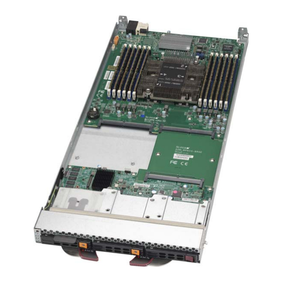
Page 55: Mainboard
Chapter 4: Blade Module Features Mainboard The mainboard of the SBI-6419P-C3N blade unit is a proprietary design, which is based on the Intel C622 chipset. See Figure 4-4 for a block diagram of this chipset and Figure 4-3 for a view of the SBI-6419P-C3N module. Figure 4-5 contains an exploded view diagram of the blade unit. - Page 56 SBI-6419P-C3N SuperBlade Module User’s Manual Figure 4-3. SBI-6419P-C3N Module...
- Page 57 Chapter 4: Blade Module Features Table 4-3. SBI-6419P-C3N Module Layout Item Description CPUs installed (see Figure 4-3 for details on CPU numbering) Front housing for three 2.5" SATA3/SSD/NVMe hard drive bays DIMM slots (see Figure 4-3 for details, twelve total) Power and Logic connectors to backplane AOM, Bridge Board USB Port...
-
Page 58: Cmos Clear
SBI-6419P-C3N SuperBlade Module User’s Manual CMOS Clear JBT1 is used to clear CMOS and will also clear any passwords. This consists of two contact pads located near the BIOS chip. Clearing CMOS 1. First power down the blade and remove it from the enclosure. 2. -
Page 59: Blade Unit Components
Chapter 4: Blade Module Features Blade Unit Components Figure 4-5. Exploded View of a SBI-6419P-C3N Blade Module Table 4-5. Main Components of a SBI-6419P-C3N Blade Module Item Description Blade Unit/Module 2.5" Hard Drives (up to three hot-swap drives) CPUs/Heatsink DIMM slots (12) Front Panel Module Cards Rear Module Cards NVMe/SATA3 Backplane... -
Page 60: Hard Disk Drives
Caution: To maintain proper airflow, both hard drive bays must have drive carriers inserted during operation whether or not a drive is installed in the tray. WARNING: Enterprise level hard disk drives are recommended for use in Supermicro chassis and servers. For information on recommended HDDs, visit the Supermicro website... -
Page 61: Chapter 5 Bios
Note: Due to periodic changes to the BIOS, some settings may have been added or deleted and might not yet be recorded in this manual. Please refer to the http:// www.supermicro.com/products/SuperBlade/module/ website for further details on BIOS setup and the BIOS menus for your SuperBlade blade module. -
Page 62: Bios Updates
However, it is recommended that you not update BIOS if you are not experiencing problems with a blade module. Updated BIOS files are located on our website(www.supermicro.com/products/ superblade/). Please check the current BIOS revision and make sure it is newer than your current BIOS before downloading. -
Page 63: Main Bios Setup
Chapter 5: BIOS Main BIOS Setup Figure 5-1. Main BIOS Setup Screen All Main Setup options are described in this section. Use the U arrow keys to move among the different settings in each menu. Use the L arrow keys to change the options for each setting. IGHT Press the <E >... - Page 64 SBI-6419P-C3N SuperBlade Module User’s Manual Table 5-1. Main BIOS Setup Menu Options Menu Option Description Using the arrow keys, highlight the month, day and year fields, and enter the System Date correct data for the system date. Press the <Enter> key to save the data. To set the system date and time, key in the correct information in the appropriate System Time fields.
-
Page 65: Advanced Setup
Chapter 5: BIOS Advanced Setup Figure 5-2. Advanced Setup Screen Choose Advanced from the BIOS Setup Utility main menu with the arrow keys to display the A menu. The items with a triangle beside them are DVANCED ETUP sub-menus that can be accessed by highlighting the item and pressing <E >. - Page 66 SBI-6419P-C3N SuperBlade Module User’s Manual Table 5-2 describes all sub-menus found in the A menu. DVANCED ETUP Table 5-2. Advanced Setup Menu Options Sub-menu Description Boot Feature Table 5-3 for a description of BIOS setup menu options in this sub-menu. CPU Configuration Table 5-4 for a description of BIOS setup menu options in this sub-menu.
- Page 67 Chapter 5: BIOS Table 5-4. CPU Configuration sub-menu Menu Option Description Processor Configuration This section shows static information on the processor configuration. Information This setting is Enabled for Windows XP and Linux (OS optimized for Hyper-threading technology), and Disabled for other OSes (any OS not Hyper-threading [ALL] optimized for Hyper-threading techology).
- Page 68 SBI-6419P-C3N SuperBlade Module User’s Manual Table 5-4. CPU Configuration sub-menu (Continued) Menu Option Description For this setting, choose a setting for the EIST PSD function. Options EIST PSD Function include HW_ALL, SW_ALL, or SW_ANY. This setting allows you to Enable or Disable the processor Turbo Mode for Turbo Mode your system.
- Page 69 Chapter 5: BIOS Table 5-5. Chipset Configuration Sub-menu (Continued) Menu Option Description Use this setting to specify if the tCCD_L is overridden by the SPD or based tCCD_L Relaxation on the memory frequency. Options include Auto, Disable and Enable. If enabled, the RD2WR Timing is overridden by optimized value. If Auto, RD2WR Timing the override only applies ti Samsung’s DIMM.
- Page 70 SBI-6419P-C3N SuperBlade Module User’s Manual Table 5-5. Chipset Configuration Sub-menu (Continued) Menu Option Description MCP1 (IIO PCIe This setting selects the PCIe port bifurcation for Br5. Options include x16 Br5) or Auto. Socket 0 PcieBr0D00F0 - Settings for these submenus are related to PCI Express Ports in your Port 0/DMI ~ system.
- Page 71 Chapter 5: BIOS Table 5-5. Chipset Configuration Sub-menu (Continued) Menu Option Description Static information for USB Module Version and USB devices connected is USB Information shown at the top of this screen. This setting allows you to enable the use of Legacy USB devices. If this option is set to Auto, legacy USB support will be automatically enabled if a legacy USB device is installed on the mainboard, and disabled if no USB Legacy USB Support...
- Page 72 SBI-6419P-C3N SuperBlade Module User’s Manual Table 5-8. PCIe/PCI/PnP Configuration Sub-menu Menu Option Description The installed version for the PCI Bus Driver is static displayed here for your PCI Bus Driver Version information. PCI Devices Common Settings Select Enabled to decode a 64-bit PCI device in the space above 4G Above 4G Decoding Address.
- Page 73 Chapter 5: BIOS Table 5-8. PCIe/PCI/PnP Configuration Sub-menu (Continued) Menu Option Description This setting allows you to Enable or Disable UEFI Network Stack for your Network Stack system. If disabled, the boot option for UEFI Network Stack will not be created.
- Page 74 SBI-6419P-C3N SuperBlade Module User’s Manual Table 5-9. SuperIO Device Configuration Sub-menu Menu Option Description This static display shows the name of the Super IO chip installed for your Super IO Chip system. Serial Port 1/2 This sub-menu allows the user the configure settings of Serial Port 1 or Configuration Serial Port 2.
- Page 75 Chapter 5: BIOS Table 5-10. Serial Port Console Redirection Sub-menu (Continued) Menu Option Description A parity bit can be sent along with regular data bits to detect data transmission errors. Select Even if the parity bit is set to 0, and the number of 1's in data bits is even.
- Page 76 SBI-6419P-C3N SuperBlade Module User’s Manual Table 5-10. Serial Port Console Redirection Sub-menu (Continued) Menu Option Description This feature allows the user to select the target terminal emulation type for Console Redirection. Select VT100 to use the ASCII character set. Select VT100+ to add color and function key support.
-
Page 77: Event Logs Setup
Chapter 5: BIOS Table 5-13. Intel(R) Virtual RAID on CPU Settings Sub-menu Menu Option Description Use this menu if you have RAID volumes or Intel VMD Controllers on the system to configure your Intel Virtual RAID on CPU settings. Otherwise this meun is blank. Event Logs Setup Figure 5-3. - Page 78 SBI-6419P-C3N SuperBlade Module User’s Manual Table 5-14. Event Logs Menu Menu Option Description Change SMBIOS This sub-menu allows you to change the SMBIOS Event Log configuration Event Log Settings settings. Change this setting to enable or disable all features of the SMBIOS SMBIOS Event Event Logging during system boot.
-
Page 79: Ipmi Setup
Chapter 5: BIOS IPMI Setup Figure 5-4. IPMI Setup Screen 5-19... - Page 80 SBI-6419P-C3N SuperBlade Module User’s Manual Table 5-15. IPMI Menu Menu Option Description IPMI Firmware Revision and IPMI Status information are statically displayed at IPMI Information the top of this menu. Selecting this sub-menu displays settings for changing the SEL Event Log System Event Log configuration.
-
Page 81: Security
Chapter 5: BIOS Security Figure 5-5. Security Setup Screen Choose Security from the BIOS Setup main menu with the arrow keys to bring up the menu. Security setting options are displayed by highlighting the setting ECURITY ETUP using the arrow keys and pressing <E >. - Page 82 SBI-6419P-C3N SuperBlade Module User’s Manual Table 5-16. Security Menu Options (Continued) Menu Option Description This setting specifies the Secure Boot Mode used. Options include Standard and Secure Boot Custom. In Custom mode, Secure Boot variables can be configured without Mode authentication.
-
Page 83: Boot
Chapter 5: BIOS Boot Figure 5-6. Boot Setup Screen Choose Boot from the 128 Mb SPI Flash EEPROM with AMI® BIOS Setup Utility main menu with the arrow keys to bring up the B menu. Security setting options ETUP are displayed by highlighting the setting using the arrow keys and pressing <E >. - Page 84 SBI-6419P-C3N SuperBlade Module User’s Manual Table 5-17. Boot Setup Menu Options Menu Option Description This setting allows you to select the boot mode to use. Options include Legacy, Boot Mode Select UEFI or Dual. This feature allows you to specify the sequence of priority for the boot device (such as hard disk drives, USB devices, CD-ROM drives, Network drives and so on).
-
Page 85: 5-10 Save & Exit
Chapter 5: BIOS 5-10 Save & Exit Figure 5-7. Save & Exit Setup Screen Choose S & E from the 128 Mb SPI Flash EEPROM with AMI® BIOS BIOS Setup Utility main menu with the arrow keys to display the S &... - Page 86 SBI-6419P-C3N SuperBlade Module User’s Manual Table 5-18. Exit Menu Options Menu Option Description Highlight this item and hit <E > to exit the BIOS Setup utility without saving NTER Discard Changes and any changes you may have made. Any changes you have made to the BIOS Exit Setup will not take effect upon system bootup.
-
Page 87: Appendix A Updating Bios Using Kvm Console
Appendix A Updating BIOS Using KVM Console Use the following procedure to update a module BIOS using the KVM console software. Updating the BIOS Using the KVM Console 1. Click on the graphic in the S -> S screen to launch the YSTEM YSTEM NFORMATION... - Page 88 SBI-6419P-C3N SuperBlade Module User’s Manual 2. In the KVM Console window, click on the V menu option from the IRTUAL TORAGE menu (Figure A-3). The V window will be displayed IRTUAL EDIA IRTUAL TORAGE (Figure A-4). Figure A-3. KVM Console Window Figure A-4.
- Page 89 Appendix A: Updating BIOS Using KVM Console 3. Under the D 1 tab of the V window, select ISO File from the EVICE IRTUAL TORAGE menu if you wish to mount an ISO file (Figure A-5). OGICAL RIVE Figure A-5. Selecting ISO File to Mount an ISO File 4.
- Page 90 SBI-6419P-C3N SuperBlade Module User’s Manual 5. After you have selected the ISO file, press the Plug In button, then the OK button to exit the V window (Figure A-7). Skip ahead to step IRTUAL TORAGE Figure A-7. Pressing the Plug In and OK Buttons for an ISO File...
- Page 91 6. If you wish instead to download the BIOS update from a USB Flash drive, then insert the flash drive into your system and select it from the Logical Drive Type menu (Figure A-8). Figure A-8. Selecting a USB Flash Drive...
- Page 92 SBI-6419P-C3N SuperBlade Module User’s Manual 7. After you have selected the USB flash drive file, press the Plug In button, then the OK button to exit the V window (Figure A-9). IRTUAL TORAGE Figure A-9. Pressing the Plug In and OK Buttons for an USB Flash Drive File...
- Page 93 8. Reboot the SuperBlade module by selecting the P -> S OWER ONTROL OWER menu option from the KVM C window. If the MicroBlade is not ESET ONSOLE powered on yet, please select S from the menu (Figure A-10). OWER Figure A-10.
- Page 94 SBI-6419P-C3N SuperBlade Module User’s Manual When the system powers up, press your keyboard’s F11 key in order to boot into the . From this list, select the ATEN Virtual CDROM YS0J NVOKE OOTABLE EVICES command. Your MicroBlade will now boot up into mounting the ISO file which contains the new BIOS file and flash utility (Figure A-11).
- Page 95 9. Close the KVM C window, or go to the Virtual Storage window (see step ONSOLE and click on Plug Out, this will remove mounting of the ISO file (Figure A-12). Figure A-12. Clicking Plug Out in the Virtual Storage Window...
- Page 96 SBI-6419P-C3N SuperBlade Module User’s Manual A-10...
- Page 97 Disclaimer The products sold by Supermicro are not intended for and will not be used in life support systems, medical equipment, nuclear facilities or systems, aircraft, aircraft devices, aircraft/emergency communication devices or other critical systems whose failure to perform be reasonably expected to result in significant injury or loss of life or catastrophic property damage.
Need help?
Do you have a question about the SuperBlade SBI-6419P-C3N and is the answer not in the manual?
Questions and answers