Table of Contents
Advertisement
Quick Links
Advertisement
Table of Contents

Related Manuals for Supermicro SBM-25G-P10


Summary of Contents for Supermicro SBM-25G-P10
- Page 1 SBM-25G-P10 Pass-Thru Module USER’S MANUAL Revision 1.0b...
- Page 2 State of California, USA. The State of California, County of Santa Clara shall be the exclusive venue for the resolution of any such disputes. Supermicro's total liability for all claims will not exceed the price paid for the hardware product.
- Page 3 If you have any questions, please contact our support team at: support@supermicro.com This manual may be periodically updated without notice. Please check the Supermicro website for possible updates to the manual revision level. Warnings Special attention should be given to the following symbols used in this manual.
-
Page 4: Table Of Contents
SBM-25G-P10 User's Manual Contents SuperBlade Pass-Thru Module Overview ..........................6 Features ..........................7 Management .........................8 Port Mapping ........................9 Internal to External Port Mapping Tables ................10 Mapping for SBE-820J with Four Pass-Thru Modules Installed ........12 Mapping for SBE-610J with Four Pass-Thru Modules Installed ........14 Mapping for SBE-414E with Two Pass-Thru Modules Installed........15... - Page 5 Super Micro Computer, Inc. 980 Rock Ave. San Jose, CA 95131 U.S.A. Tel: +1 (408) 503-8000 Fax: +1 (408) 503-8008 Email: marketing@supermicro.com (General Information) support@supermicro.com (Technical Support) Website: www.supermicro.com Europe Address: Super Micro Computer B.V. Het Sterrenbeeld 28, 5215 ML...
-
Page 6: Superblade Pass-Thru Module
SuperBlade Pass-Thru Module Overview The Supermicro SBM-25G-P10 Pass-Thru Module is designed for Supermicro SuperBlade enclosures for high performance datacenter traffic application usage. It is compatible with the SuperBlade 8U (SBE-820J), 6U (SBE-610J), and 4U (SBE-414E) enclosures. Up to four modules can be used in the 8U or 6U enclosure, and up to two in the 4U enclosure. -
Page 7: Features
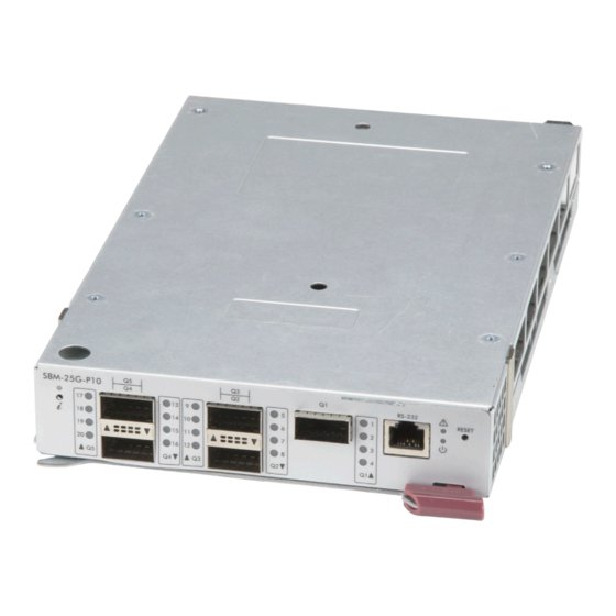
Features Features • Twenty internal 25G/10G downlink ports mapped from server node to external QSFP connection • Up to twenty external 25G/10G uplink ports through the five QSFP28 ports • Auto-configuration of the port speed • Minimal configuration and management through the Chassis Management Module (CMM) QSFP28 Ports UID LED Console Port... -
Page 8: Management
SBM-25G-P10 User's Manual Management The SBM-25G-P10 module is managed through the CMM module web interface. It supports the upload of configuration files, as described later in this manual. Note that CMM version 3.55 or later is required. The module can be connected to any computer using the RS-232 Console port. This is generally used to collect debug logs for the Supermicro Technical Support team. -
Page 9: Port Mapping
Port Mapping Port Mapping The port mapping between the blade server and the switch external port varies depending on the model of the enclosure. The on-board dual port NIC card and the optional add-on mezzanine card with dual ports have internal mapping to the pass-thru module as shown below. -
Page 10: Internal To External Port Mapping Tables
SBM-25G-P10 User's Manual Internal to External Port Mapping Tables In the tables below, the following identifiers are used: Module Slot – A1, A2, B1 and B2 refer to the modules and their slot number. (Shown for the SBE-610J enclosure with four pass-thru modules.) - Page 11 Port Mapping External Port – Q1 to Q5 refer to the external QSFP28 ports on the pass-thru module. External Port LED – This is the QSFP28 (Q1 to Q5) port LED number (split) on the module front panel. External Port LED Number 1-20 External QSFP28 Ports Q1-Q5 Figure 6.
-
Page 12: Mapping For Sbe-820J With Four Pass-Thru Modules Installed
SBM-25G-P10 User's Manual Mapping for SBE-820J with Four Pass-Thru Modules Installed Port Mapping Blade Slot External Port Module Slot External Port Cable Link LED Number On Board - NIC 1 C / 3 On Board - NIC 2 C / 3... - Page 13 Port Mapping Port Mapping Blade Slot External Port Module Slot External Port Cable Link LED Number On Board - NIC 1 D / 4 On Board - NIC 2 D / 4 Mezzanine - NIC 3 A / 1 Mezzanine - NIC 4 A / 1 On Board - NIC 1 B / 2...
-
Page 14: Mapping For Sbe-610J With Four Pass-Thru Modules Installed
SBM-25G-P10 User's Manual Mapping for SBE-610J with Four Pass-Thru Modules Installed Port Mapping Blade Slot External Port Module Slot External Port Cable Link LED Number On Board - NIC 1 B / 2 On Board - NIC 2 B / 2... -
Page 15: Mapping For Sbe-414E With Two Pass-Thru Modules Installed
Port Mapping Mapping for SBE-414E with Two Pass-Thru Modules Installed Port Mapping Blade Slot External Port Module Slot External Port Cable Link LED Number On Board - NIC 1 B / 2 On Board - NIC 2 B / 2 On Board - NIC 1 A / 1 On Board - NIC 2... -
Page 16: Firmware And Configuration File Upload
CMM Web interface (version 3.55 or later is required). The procedure below applies for both configuration file and firmware upgrade. Note: Contact Supermicro Technical Support to get the appropriate configuration file or in case the external ports link does not come up. - Page 17 Firmware and Configuration File Upload 3. Scroll further down to the Pass-Thru Firmware/Configuration Upgrade section in the Switch Summary page. Figure 10. File Upgrade/Update Section 4. Fill in the file information. TFTP server IP Address: The configuration file must be available in a TFTP server for download.
-
Page 18: Specifications
SBM-25G-P10 User's Manual 6 Specifications Module Hardware Specifications Maximum Internal ports: Twenty 10G/25G Internal Ports External Ports: Five QSFP28/100G ports that can split into four 25G/SFP28 or four 10G/ SFP+ using Fan-out cables Console Port: One (RJ45 based) Physical and Environmental Specifications Weight: 1.99lbs (0.902Kg) Dimensions: 6 1/2”...
Need help?
Do you have a question about the SBM-25G-P10 and is the answer not in the manual?
Questions and answers