Table of Contents
Advertisement
Quick Links
Advertisement
Table of Contents

Related Manuals for Supermicro SBI-7126TG


Summary of Contents for Supermicro SBI-7126TG
- Page 1 SBI-7126TG Blade Module User’s Manual Revison 1.0a...
- Page 2 This product, including software and documentation, is the property of Supermicro and/or its licensors, and is supplied only under a license. Any use or reproduction of this product is not allowed, except as expressly permitted by the terms of said license.
- Page 3 Chapter 3: Setup and Installation Refer to this chapter for details on installing the SBI-7126TG blade module into the Superblade chassis. Other sections cover the installation and placement of memory modules and the installation of hard disk drives into the blade module.
- Page 4 SBI-7126TG Blade Module User’s Manual Notes...
-
Page 5: Table Of Contents
........1-1 1-3 Blade Module Features ..............1-2 Processors ....................1-2 Memory ....................1-3 Storage....................1-3 Density ....................1-3 1-4 Contacting Supermicro ..............1-5 Chapter 2 System Safety ..............2-1 2-1 Electrical Safety Precautions ............2-1 2-2 General Safety Precautions ............. - Page 6 SBI-7126TG Blade Module User’s Manual LED Indicators ..................4-3 KVM Connector..................4-3 4-2 Mainboard ................... 4-4 Jumpers ....................4-6 CMOS Clear.................... 4-6 USB Port Connector ................4-6 4-3 Blade Unit Components ..............4-7 Memory Support ..................4-8 Hard Disk Drives ..................4-8 Chapter 5 BIOS ..................
- Page 7 Figure 4-1. SBI-7126TG Blade Module Front View........... 4-1 Figure 4-2. Blade Control Panel................ 4-2 Figure 4-3. B8DTG Mainboard................4-4 Figure 4-4. Intel IOH36D + ICH10 Chipset Block Diagram ....... 4-5 Figure 4-5. Exploded View of SBI-7126TG Blade Module ........ 4-7...
- Page 8 SBI-7126TG Blade Module User’s Manual Notes...
- Page 9 Table 4-3. Blade Module LED Indicators ............4-3 Table 4-4. B8DTG Mainboard Layout ............... 4-5 Table 4-5. Main Components of SBI-7126TG Blade Module......4-8 Table 5-1. Main BIOS Setup Menu Options............5-4 Table 5-2. Advanced Setup Menu Options ............5-4 Table 5-3.
- Page 10 SBI-7126TG Blade Module User’s Manual Notes...
-
Page 11: Chapter 1 Introduction
Chapter 1 Introduction Overview The SBI-7126TG blade module is a compact self-contained server that connects into a pre-cabled enclosure that provides power, cooling, management and networking functions. One enclosure for the SBI-7126TG blade module can hold ten blade units. In this manual, “blade system” refers to the entire system (including the enclosure and blades units), “blade”... -
Page 12: Blade Module Features
Please note that you will need to check the detailed specifications of a particular blade module for a list of the CPUs it supports. Details on installation of the processor into the SBI-7126TG blade module are found in Chapter 3: "Setup and Installation" on page... -
Page 13: Memory
Chapter 1: Introduction Memory The SBI-7126TG blade module has six 240-pin DIMM sockets that can support up to 96 GBECC Registered DDR3-1333/1066/800 SDRAM. Both interleaved and non-interleaved memory are supported, so you may populate any number of DIMM slots. Please refer to the Supermicro web site for a list of supported memory (www.supermicro.com/products/superblade). -
Page 14: Figure 1-1. Full Rack Of Blade Enclosures And Blade Servers
SBI-7126TG Blade Module User’s Manual Figure 1-1. Full Rack of Blade Enclosures and Blade Servers... -
Page 15: Contacting Supermicro
Address: Super Micro Computer, Inc. 980 Rock Ave. San Jose, CA 95131 U.S.A. Tel: +1 (408) 503-8000 Fax: +1 (408) 503-8008 marketing@supermicro.com (General Information) Email: support@supermicro.com (Technical Support) Web Site: www.supermicro.com Europe Address: Super Micro Computer B.V. Het Sterrenbeeld 28, 5215 ML ‘s-Hertogenbosch, The Netherlands... - Page 16 SBI-7126TG Blade Module User’s Manual Notes...
-
Page 17: Chapter 2 System Safety
Chapter 2 System Safety Electrical Safety Precautions Basic electrical safety precautions should be followed to protect yourself from harm and the SuperBlade from damage: • Be aware of how to power on/off the enclosure power supplies and the individual blades as well as the room's emergency power-off switch, disconnection switch or electrical outlet. -
Page 18: General Safety Precautions
SBI-7126TG Blade Module User’s Manual General Safety Precautions Follow these rules to ensure general safety: • Keep the area around the SuperBlade clean and free of clutter. • Place the blade module cover and any system components that have been removed away from the system or on a table so that they won't accidentally be stepped on. -
Page 19: Chapter 3 Setup And Installation
This chapter covers the setup and installation of the blade module and its components. Installing Blade Modules Up to ten SBI-7126TG blade modules may be installed into a single blade enclosure (depending upon your enclosure and blad). Blade modules with Windows and Linux operating systems may be mixed together in the same blade enclosure. -
Page 20: Removing/Replacing The Blade Cover
NOTE: The below illustrations in Figure 3-1 Figure 3-2 demonstrate the removal and insertion for all Supermicro blade modules. Your blade module or enclosure may appear different than illustrated but uses the same handles and method of insertion. -
Page 21: Figure 3-1. Inserting A Blade Into The Enclosure
Chapter 3: Setup and Installation Figure 3-1. Inserting a Blade into the Enclosure Figure 3-2. Locking the Blade into Position... -
Page 22: Processor Installation
SBI-7126TG Blade Module User’s Manual Processor Installation One or two processors may be installed to the mainboard of each blade unit. See Chapter 1 for general information on the features of the blade unit and the Supermicro web site for further details including processor, memory and operating system support. - Page 23 Chapter 3: Setup and Installation 7. Once the CPU is securely seated in the socket, lower the CPU load plate to the socket. 8. To install the heatsink, apply thermal grease to the top of the processor. (If reinstalling a heatsink, first clean off the old thermal grease with a clean, lint-free cloth.) 9.
-
Page 24: Figure 3-3. Installing A Processor In A Socket
SBI-7126TG Blade Module User’s Manual Figure 3-3. Installing a Processor in a Socket Align CPU Keys with Socket... -
Page 25: Onboard Battery Installation
WARNING: For all SBI-7426 series blades, ONLY VLP (Very low profile) memory can be used. Populating Memory Slots The mainboard of a SBI-7126TG blade module has 6 memory slots, depending upon the blade model. Both interleaved and non-interleaved memory are supported, so you may populate any number of DIMM slots. -
Page 26: Figure 3-5. 6-Slot Dimm Numbering
SBI-7126TG Blade Module User’s Manual Table 3-1. Populating Twelve Memory Slots for Interleaved Operation Processor 1 Processor 2 Number of DIMMs Channel 0 Channel 1 Channel 2 Channel 0 Channel 1 Channel 2 2 DIMMs 4 DIMMs 6 DIMMs NOTE: The DIMM slot number specified in... -
Page 27: Dimm Installation
"Powering Up a Blade Unit" on page 3-1). Hard Drive Installation The SBI-7126TG blade module does not mount a hard disk drive system. However you may install an optional SATA DOM module for file or operating system storage. See "Hard Disk Drives" on page 4-8... -
Page 28: Installing Gpu Expansion Cards
SBI-7126TG Blade Module User’s Manual Installing GPU Expansion Cards If you need to install GPU extension cards into the SBI-7126TG blade module, then you must first remove the top cover, and then the Blade Module Front Assembly and GPU PCI-E Expansion Card Bracket first (see Figure 3-7). -
Page 29: Figure 3-8. Remove The Top Blade Cover
Chapter 3: Setup and Installation Installing GPU Cards in the Blade Module 1. Unscrew the retaining screw on the top cover of the blade module and remove the top cover from the module (see Figure 3-8). Figure 3-8. Remove the Top Blade Cover 3-11... -
Page 30: Figure 3-9. Remove Front Blade Assembly
SBI-7126TG Blade Module User’s Manual 2. Remove the fourteen (14) retaining screws for the module’s riser card and assembly front and lift off the front assembly (see Figure 3-9 Figure 3-10). Figure 3-9. Remove Front Blade Assembly Figure 3-10. Front Assembly... -
Page 31: Figure 3-11. Remove I/O Plates From Gpu Front Assembly
Chapter 3: Setup and Installation 3. Remove the two I/O plates from the front assembly by removing their retaining screws (four screws per GPU card) and detaching them. 4. Replace with the new front I/O plates (part # MCP-120-00056-0N) shipped in the blade accessory kit, with three front screws (see Figure 3-11). -
Page 32: Figure 3-12. Re-Attach I/O Plates
SBI-7126TG Blade Module User’s Manual 6. The completed assembly will have the GPU cards connected to the to the Supermicro I/O plates and the I/O cards connected to the riser card’s PCI-E connectors (see Figure 3-12 for completed assembly). Figure 3-12. Re-attach I/O Plates... -
Page 33: Figure 3-13. Attaching Retention Brackets To Gpu Cards
Figure 3-13. Attaching Retention Brackets to GPU Cards NOTE: The SBI-7126TG blade module uses a different size and type of brackets for each of the GPUs installed in the module. Use (part #... - Page 34 SBI-7126TG Blade Module User’s Manual Notes 3-16...
-
Page 35: Chapter 4 Blade Module Features
Chapter 4 Blade Module Features Figure 4-1. SBI-7126TG Blade Module Front View This chapter describes the SBI-7126TG blade module. Installation and maintenance should be performed by experienced technicians only. Figure 4-1 for a front view of the blade unit and Table 4-1 for its features. -
Page 36: Control Panel
SBI-7126TG Blade Module User’s Manual Control Panel Each blade has a similar control panel (Figure 4-2) with power on/off button, a KVM connector, a KVM button and four LEDs on the top front of the unit. The numbers mentioned in... -
Page 37: Power Button
Chapter 4: Blade Module Features Power Button Each blade has its own power button so that individual blade units within the enclosure may be turned on or off independently of the others. Press the power button (#1) to turn on the blade server. The power LED (#3) will turn green. To turn off, press and hold the power button for >4 seconds and the power LED will turn orange. -
Page 38: Mainboard
SBI-7126TG Blade Module User’s Manual Mainboard The mainboard of the SBI-7126TG blade unit is a proprietary design, which is based on the Intel IOH36D + ICH10 chipset. See Figure 4-4 for a block diagram of this chipset, Figure 4-3 for a view of the B8DTG Mainboard and... -
Page 39: Figure 4-4. Intel Ioh36D + Ich10 Chipset Block Diagram
Chapter 4: Blade Module Features Table 4-4. B8DTG Mainboard Layout Item Description LGA 1366 CPU1 Socket LGA 1366 CPU2 Socket DIMM Slots (see Figure 3-5: "6-Slot DIMM Numbering" on page 3-8 for details) InfiniBand Connectors (for InfiniBand cards or 10G card) Gbx Connectors (for power and logic to backplane) Intel IOH36D + ICH10 Onboard Battery... -
Page 40: Jumpers
3. Replace the cover, install the blade back into the enclosure and power it on. USB Port Connector The SBI-7126TG blade module includes an internal USB Type A port that you may use for connecting USB devices to the blade module when the top blade cover is removed. -
Page 41: Blade Unit Components
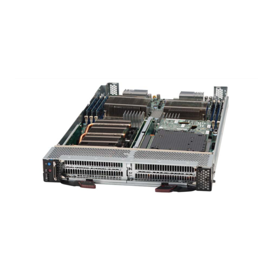
Chapter 4: Blade Module Features Blade Unit Components Figure 4-5. Exploded View of SBI-7126TG Blade Module Main components of the SBI-7126TG blade module are shown in Figure 4-5 described in Table 4-5. -
Page 42: Memory Support
PCI-E 2.0 x16 GPU Expansion Card Bracket and Blade Module Front Assembly Adapter Card Bracket Memory Support The SBI-7126TG blade module supports up to 96 GB of ECC Registered DDR3-1333/ 1066/800 SDRAM in twelve DIMM sockets. See Section 3-5 for further details on mainboard memory installation. -
Page 43: Chapter 5 Bios
NOTE: Due to periodic changes to the BIOS, some settings may have been added or deleted and might not yet be recorded in this manual. Please refer to http://www.supermicro.com/products/SuperBlade/module/ web site for further details on BIOS setup and the BIOS menus for your SuperBlade blade module. -
Page 44: Bios Updates
SBI-7126TG Blade Module User’s Manual BIOS Updates It may be necessary to update the BIOS used in the blade modules on occasion. However, it is recommended that you not update BIOS if you are not experiencing problems with a blade module. -
Page 45: Running Setup
Chapter 5: BIOS 3. Go to the V menu and select F IRTUAL EDIA LOPPY MAGE PLOAD 4. B or O to locate the *.img file on your desktop and select it. ROWSE 5. Press the U button and wait a few seconds for the image to upload to the PLOAD CMM. -
Page 46: Main Bios Setup
SBI-7126TG Blade Module User’s Manual Main BIOS Setup All Main Setup options are described in this section. Use the U arrow keys to move among the different settings in each menu. Use the L arrow keys to change the options for each setting. -
Page 47: Table 5-3. Boot Feature Sub-Menu
Chapter 5: BIOS Table 5-2. Advanced Setup Menu Options (Continued) Sub-menu Description SuperIO Device Table 5-8 for a description of BIOS setup menu options in this sub-menu. Configuration Remote Access Table 5-9 for a description of BIOS setup menu options in this sub-menu. Configuration System Health Table 5-10... -
Page 48: Table 5-4. Processor & Clock Options Sub-Menu
SBI-7126TG Blade Module User’s Manual Table 5-4. Processor & Clock Options Sub-menu Menu Option Description This setting allows you to set the CPU Ratio to either Auto (Maximum Ratio) or CPU Ratio Manual (Manual Ratio). Clock Spread This setting enables or disables spread spectrum modulation. Options are Spectrum Enabled and Disabled. -
Page 49: Table 5-5. Advanced Chipset Control Sub-Menu
Chapter 5: BIOS Table 5-4. Processor & Clock Options Sub-menu (Continued) Menu Option Description Intel (R) TurboMode This setting allows the processor cores to run faster than the marked frequency Tech in specific conditions. Options are either Enabled or Disabled. This setting should be enabled in order to enable or disable the “Enhanced Halt C1E Support State”... - Page 50 SBI-7126TG Blade Module User’s Manual Table 5-5. Advanced Chipset Control Sub-menu (Continued) Menu Option Description This setting sets the system memory mode. Options include the following: • Independent (default) – All DIMMs are available to the operating system. • Channel Mirror – The mainboard maintains two identical copies of all data in memory for redundancy.
-
Page 51: Table 5-6. Ide/Sata Configuration Sub-Menu
Chapter 5: BIOS Table 5-5. Advanced Chipset Control Sub-menu (Continued) Menu Option Description USB 2.0 This setting is only active if USB Functions above it is Disabled. This setting Controller allows you to Enable or Disable the USB 2.0 controller in your system. This option allows you to enable the use of Legacy USB devices. -
Page 52: Table 5-7. Pci/Pnp Configuration Sub-Menu
SBI-7126TG Blade Module User’s Manual Table 5-6. IDE/SATA Configuration Sub-menu (Continued) Menu Option Description Self-Monitoring Analysis and Reporting Technology (SMART) can help predict impending drive failures. Select “Auto” to allow BIOS to auto detect hard disk S.M.A.R.T. drive support. Select “Disabled” to prevent AMI BIOS from using the S.M.A.R.T. -
Page 53: Table 5-8. Superio Device Configuration Sub-Menu
Chapter 5: BIOS Table 5-8. SuperIO Device Configuration Sub-menu Menu Option Description This option specifies the base I/O port address and the Interrupt Request address of Serial Port 1. Select Disabled to prevent the serial port from accessing any system resources. When this option is Disabled, the serial port Serial Port1 Address physically becomes unavailable. -
Page 54: Table 5-10. System Health Monitor Sub-Menu
SBI-7126TG Blade Module User’s Manual Table 5-10. System Health Monitor Sub-menu Menu Option Description This sub-menu contains system health information for the following: • CPU1 Temperature • CPU2 Temperature • System Temperature • CPU1 Vcore • CPU2 Vcore System Health •... -
Page 55: Table 5-12. Ipmi Configuration Sub-Menu
Chapter 5: BIOS Table 5-12. IPMI Configuration Sub-menu Menu Option Description The Baseboard Management Controller (BMC) manages the interface between the system management software and platform hardware. The tope of this menu BMC Information contains non-configurable information that shows the IPMI Firmware Revision and the status of the BMC micro controller. -
Page 56: Table 5-13. Event Log Configuration Sub-Menu
SBI-7126TG Blade Module User’s Manual Table 5-12. IPMI Configuration Sub-menu (Continued) Menu Option Description Current IP Address in This static display shows the current IP address used for your IPMI connection. Subnet masks tell the network which subnet this system belongs. The value of Subnet Mask... -
Page 57: Security
Chapter 5: BIOS Table 5-13. Event Log Configuration Sub-menu (Continued) Menu Option Description This setting clears the Event Log memory of all messages. Options are OK and Clear Event Log Cancel. This setting allows you to specify whether or not you wish to record a PCIE Error PCIE Error Log Log. -
Page 58: Exit
SBI-7126TG Blade Module User’s Manual Table 5-15. Boot Setup Menu Options Menu Option Description This sub-menu feature allows you to specify the sequence of priority for the boot device (such as hard disk drives, USB devices, CD-ROM drives, Network drives and so on). -
Page 59: Appendix Abios Post Codes
Appendix A BIOS POST Codes BIOS POST Messages During the Power-On Self-Test (POST), the BIOS will check for problems. If a problem is found, the BIOS will activate an alarm or display a message. The following is a list of such BIOS messages. - Page 60 SBI-7126TG Blade Module User’s Manual Table A-1. BIOS POST Messages (Continued) BIOS Message Description Previous POST did not complete successfully. POST loads default values and offers to run Setup. If the failure was caused by incorrect values and they are not corrected, the next boot Previous boot incomplete - Default will likely fail.
- Page 61 Appendix A: BIOS POST Codes Table A-1. BIOS POST Messages (Continued) BIOS Message Description Where nnnn is the amount of RAM in kilobytes successfully nnnn kB Extended RAM Passed tested. Where nnnn is the amount of system cache in kilobytes nnnn Cache SRAM Passed successfully tested.
-
Page 62: Recoverable Post Errors
SBI-7126TG Blade Module User’s Manual BIOS POST Codes This section lists the POST (Power-On Self-Test) codes for the AMI BIOS. POST codes are divided into two categories: recoverable and terminal. Recoverable POST Errors When a recoverable type of error occurs during POST, the BIOS will display an POST code that describes the problem. - Page 63 Appendix A: BIOS POST Codes Table A-2. Terminal POST Errors (Continued) Post Code Description 8237 DMA controller initialization Reset Programmable Interrupt Controller 1-3-1-1 Test DRAM refresh 1-3-1-3 Test 8742 Keyboard Controller Auto size DRAM Initialize POST Memory Manager Clear 512 kB base RAM 1-3-4-1 RAM failure on address line xxxx* 1-3-4-3 RAM failure on data bits xxxx* of low byte of memory bus Enable cache before system BIOS shadow...
- Page 64 SBI-7126TG Blade Module User’s Manual Table A-2. Terminal POST Errors (Continued) Post Code Description Initialize POST display service Display prompt “Press F2 to enter SETUP” Disable CPU cache Test RAM between 512 and 640 kB Test extended memory Test extended memory address lines...
- Page 65 Appendix A: BIOS POST Codes Table A-2. Terminal POST Errors (Continued) Post Code Description Initialize hard-disk controllers Initialize local-bus hard-disk controllers Jump to UserPatch2 Build MPTABLE for multi-processor boards Install CD ROM for boot Clear huge ES segment register 1-2 Search for option ROMs. One long, two short beeps on check-sum failure Check for SMART Drive (optional) Shadow option ROMs Set up Power Management...
-
Page 66: Table A-3. Boot Block Flash Rom Terminal Post Errors
SBI-7126TG Blade Module User’s Manual Table A-2. Terminal POST Errors (Continued) Post Code Description Initialize POST Error Manager (PEM) Initialize error logging Initialize error display function Initialize system error handler PnPnd dual CMOS (optional) Initialize note dock (optional) Initialize note dock late... - Page 67 Appendix A: BIOS POST Codes Table A-3. Boot Block Flash ROM Terminal POST Errors (Continued) Post Code Description System memory test Initialize interrupt vectors Initialize Run Time Clock Initialize video Initialize System Management Manager Output one beep Clear Huge Segment Boot to Mini DOS Boot to Full DOS If the BIOS detects error 2C, 2E, or 30 (base 512K RAM error), it displays an additional...
- Page 68 SBI-7126TG Blade Module User’s Manual Notes A-10...
- Page 69 Disclaimer The products sold by Supermicro are not intended for and will not be used in life support systems, medical equipment, nuclear facilities or systems, aircraft, aircraft devices, aircraft/emergency communication devices or other critical systems whose failure to perform be reasonably expected to result in significant injury or loss of life or catastrophic property damage.
- Page 70 SBI-7126TG Blade Module User’s Manual Notes...
Need help?
Do you have a question about the SBI-7126TG and is the answer not in the manual?
Questions and answers