Advertisement
Quick Links
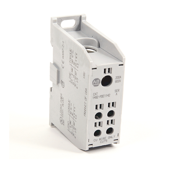
Installation Instructions
Enclosed Power Blocks
Bloc d'alimentation protégé
Eingeschlossener Stromblock
Morsetto di potenza con guscio
Bloque de potencia con protección
Catalog Numbers 1492-PDE1_ _ _
WARNING
AVERTISSEMENT
WARNUNG
AVVERTENZA
ADVERTENCIA
Catalog
Termination
Number
1492-PDE1112
1492-PDE1C112
B - C
Stranded
G , H
Line/Load
Wire
Solid Wire
1492-PDE1142
B - C
1492-PDE1C142
G , H
Stranded
Line
Wire
Solid Wire
B - C
Stranded
Wire
G , H
Load
Solid Wire
1.11
(28.2)
3.00
(76.2)
1.11
(28.2)
To prevent electrical shock, disconnect from power source before installing
or servicing.
Avant le montage et la mise en service, couper l'alimentation secteur pour
éviter toutes décharges.
Vor Installations- oder Servicearbeiten Stromversorgung unterbrechen, um
Elektroschocks zu vermeiden.
Per prevenire infortuni, togliere tensione prima dell'installazione o
manutenzione.
Desconéctese de la corriente eléctrica, antes de la instalación o del servicio,
a fin de impedir sacudidas eléctricas.
Connector
Wire
Wire Range
Hole
Strip
(English - AWG)
Diameter
Length
Size
3/0 - 8
10 - 14
7/8 in
2/0 - 8
0.531 in
22 mm
2/0 - 8
I
10 - 14
10 - 14
3/0 - 8
10 - 14
2/0 - 8
7/8 in
0.531 in
22 mm
2/0 - 8
I
10 - 14
10 - 14
2 - 8
10 - 14
11/16 in
4 - 8
0.312 in
17.3 mm
4 - 8
I
10 - 14
10 - 14
3.33
(84.5)
2.22
(56.4)
2.22
(56.4)
LISTED
Made in USA
Voltage: 600V AC/DC (UL/CSA)
Current: 200 Amps (Cu Wire only)
Torque
Hex
SCCR Ratings (Default 10kA Rating unless shown in table below)
-0, +10%
Drive
Size
lb-in / Nm
180 / 20.3
Wire Range (AWG)
Wire Type
50 / 5.6
(Class)
Line
180 / 20.3
6 mm
3/0 - 8
B - C
180 / 20.3
2/0 - 8
G - I
50 / 5.6
50 / 5.6
Minimum Enclosure Size: 16 x 12 x 6 in.
180 / 20.3
50 / 5.6
Wire Range (AWG)
180 / 20.3
Wire Type
6 mm
180 / 20.3
(Class)
Line
50 / 5.6
3/0 - 8
50 / 5.6
B - C
50 / 5.6
3/0 - 8
40 / 4.5
G - H
2/0 - 8
50 / 5.6
2/0 - 8
4 mm
I
50 / 5.6
2/0 - 8
40 / 4.5
Minimum Enclosure Size: 16 x 12 x 4 in.
40 / 4.5
3.62
(92.0)
#10 Ø (M5)
20 lb-in (2.6 Nm)
3JUU
1000V AC/DC (CE)
Max Fuse Protection Req.
Amp Rating / Class
J
T
RK1 RK5
G
CC
Load
3/0 - 8
225 225
200 60 60
30
2/0 - 8
300 300 200 100 60
30
Max Fuse Protection Req .
Amp Rating / Class
J
T
RK1 RK5
G
CC
Load
2 - 8
225 225 200 60 60
30
8 - 14
100 110
100 30 60
30
4 - 8
225
225
200
60
60
30
4 - 8
225
225
200
60
60
30
8 - 12
100 110 100 30 60
30
2.70
(69.0)
IEC
60947-7-1
SCCR RMS Sym.
Amps 600V Max.
100,000
SCCR RMS Sym.
Amps 600V Max.
100,000
Advertisement

Subscribe to Our Youtube Channel
Related Manuals for Allen-Bradley 1492-PDE1112


Summary of Contents for Allen-Bradley 1492-PDE1112
-
Page 1: Installation Instructions
-0, +10% Drive (English - AWG) Number Diameter Size Length lb-in / Nm Size 1492-PDE1112 3/0 - 8 180 / 20.3 Max Fuse Protection Req. Wire Range (AWG) SCCR RMS Sym. 1492-PDE1C112 B - C Wire Type Amp Rating / Class 10 - 14 50 / 5.6... - Page 2 Please note: Once these devices are ganged together, they can not be separated. A noter: une fois que ces dispositifs sort assemblés, il est impossible de les séparer. Hinweis: Verbundene Geräte können nicht mehr getrennt werden. Nota: una volta montati in serie, questi dispositivi non possono essere separati. Nota: una vez que se hayan unido estos dispositivos, no podrán separarse.
Need help?
Do you have a question about the 1492-PDE1112 and is the answer not in the manual?
Questions and answers