Advertisement
Quick Links
Installation Instructions
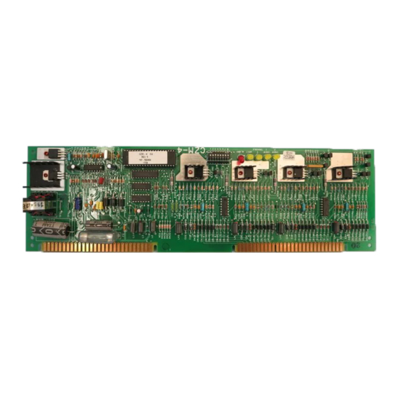
Model CZM-4
Conventional Zone Module
OPERATION
The Model CZM-4 Conventional Zone Module from
Siemens Building Technologies, Inc. is used with the
MXL to provide four Class A (Style D) or Class B
(Style B) conventional initiating device circuits. Each
circuit can monitor up to thirty 2-wire photoelectric or
ionization smoke detectors and an unlimited number
of normally open contact devices. Projected beam
and flame detectors, detector relay bases, and
remote indicator lamps may also be used with the
CZM-4.
Activation of any device on the circuit initiates
a zone alarm and causes any previously pro-
grammed functions to operate. Any circuit in
alarm or trouble condition is identified by a user-
specified, 32-character, alphanumeric message
displayed on the MXL LCD annunciator.
The CZM-4 is designed to function in a local de-
grade mode during failure of the MXL main proces-
sor or during the loss of the System communication
network. While in the degrade mode, the CZM-4 can
report both alarm and trouble conditions and can
activate local outputs on other modules within the
same enclosure.
Note: When verification is used on a CZM-4
zone, do not use shorting devices on
that circuit.
Any or all of the CZM-4 circuits may be programmed
to operate with Alarm Verification.
This allows the automatic verification of alarm
conditions caused by smoke detectors in order to
prevent nuisance alarms.
Siemens Building Technologies, Inc.
8 Fernwood Road
Florham Park, New Jersey 07932
P/N 315-090726-12
The CZM-4 has five LEDs which indicate alarm,
transmit, trouble, and two user programmable
functions, respectively.
For additional information on the MXL/MXLV
System, refer to the MXL/MXLV Manual, P/N 315-
092036.
INSTALLATION
Remove all system power before installation,
first battery and then AC. (To power up, first
connect the AC and then the battery.)
The CZM-4 module plugs into two half-width slots,
forming one full slot on the MOM-4 (See Figure 1).
As many as two CZM-4 modules may be plugged
into a MOM-4 Card Cage.
Each CZM-4 can be in either the upper or lower
slots of the MOM-4. The position it is in deter-
mines whether the device loops are on TB1 or
TB2 of the MOM-4.
Setting the Address
Before the CZM-4 is installed into the MOM-4,
set the network address on switch S1 (See
Figure 2). Set the address to the one selected in
the CSG-M for this particular CZM-4. Follow the
switch positions in Table 1 on the back to set
the address.
Siemens Building Technologies, Ltd.
2 Kenview Boulevard
Brampton, Ontario L6T 5E4 Canada
Fire Safety
Advertisement

Subscribe to Our Youtube Channel
Related Manuals for Siemens CZM-4


Summary of Contents for Siemens CZM-4
- Page 1 MOM-4 (See Figure 1). As many as two CZM-4 modules may be plugged The CZM-4 is designed to function in a local de- into a MOM-4 Card Cage. grade mode during failure of the MXL main proces-...
- Page 2 Figure 1 MOM-4 PC Board Mounting the CZM-4 After the address is set, install the CZM-4 into the MOM-4 module, being sure that the CZM-4 is firmly seated in the card edge connector. ELECTRICAL RATINGS 3 / I i t c i t c ‡...
- Page 3 MXL, MXL-IQ and MXLV 6. Maximim resistance: 70 ohms/circuit. Systems, P/N 315-091772 7. The PBA-1191 requires Rev. 3 or higher of CZM-4 software. revision 6 or higher, for 8. Positive and negative ground fault detected at <20 ohms for terminals 1-16.
- Page 4 TABLE 1 NETWORK ADDRESS PROGRAMMING 8 76 5 43 21 8 7 6 5 4 3 2 1 8 7 6 5 4 3 2 1 8 7 6 5 4 3 2 1 ADDR ADDR ADDR ADDR ILLEGAL OXOOOOOO XOOOOOOO XXOOOOOO ILLEGAL...
Need help?
Do you have a question about the CZM-4 and is the answer not in the manual?
Questions and answers