Table of Contents
Advertisement
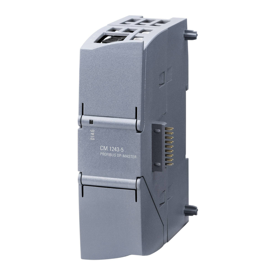
CM 1243-
5
SIMATIC NET
CM 1243-5
Operating Instructions
04/2011
C79000-G8976-C246-01
___________________
Preface
___________________
Application and properties
___________________
Displays and connectors
Installing, connecting up and
___________________
commissioning
Configuration and
___________________
programming
___________________
Operating the module
___________________
Technical specifications
___________________
Dimension drawings
___________________
Approvals
___________________
References
___________________
Training, Service & Support
1
2
3
4
5
6
A
B
C
D
Advertisement
Table of Contents

Related Manuals for Siemens CM 1243-5


Summary of Contents for Siemens CM 1243-5
- Page 1 CM 1243- Preface ___________________ Application and properties ___________________ Displays and connectors SIMATIC NET Installing, connecting up and ___________________ commissioning Configuration and ___________________ CM 1243-5 programming ___________________ Operating the module Operating Instructions ___________________ Technical specifications ___________________ Dimension drawings ___________________ Approvals ___________________...
- Page 2 Note the following: WARNING Siemens products may only be used for the applications described in the catalog and in the relevant technical documentation. If products and components from other manufacturers are used, these must be recommended or approved by Siemens. Proper transport, storage, installation, assembly, commissioning, operation and maintenance are required to ensure that the products operate safely and without any problems.
-
Page 3: Preface
1. Product name In this document, the term "CM" is also used instead of the full product name "CM 1243-5". Purpose of the manual This manual describes the properties of this module and supports you when installing and commissioning the device. - Page 4 The acceptance of the disclaimers of liability and warranty it contains is a clear precondition of the use of open source software. You will find the license conditions on the data medium with the product documentation. CM 1243-5 Operating Instructions, 04/2011, C79000-G8976-C246-01...
-
Page 5: Table Of Contents
Electrical connections ........................15 Installing, connecting up and commissioning ................... 17 Warning overvoltage protection ....................19 Installing and commissioning the CM 1243-5 ................19 Pin assignment of the socket for the external power supply ............22 Pinout of the D-sub socket......................23 Configuration and programming ......................25 Configuration..........................25... - Page 6 Table of contents CM 1243-5 Operating Instructions, 04/2011, C79000-G8976-C246-01...
-
Page 7: Application And Properties
Operates as DP slave ● CM 1243-5 Operates as DP master class 1 If a CM 1242-5 and a CM 1243-5 are installed together, an S7-1200 can perform the following tasks simultaneously: ● Slave of a higher-level DP master system ●... -
Page 8: Performance Data
1.3 Performance data ● S7-300/400 with PROFIBUS CP (for example CP 342-5) ● SIMATIC PC stations with PROFIBUS CP Types of communication with the CM 1243-5 in DP-V1 The following types of communication are available with DP-V1: ● Cyclic communication The CM supports cyclic communication for the transfer of process data between DP slave and DP master. -
Page 9: Requirements For Operation
16 DP slaves in total per station. If you plug in a master module (CM 1243-5) and 1 or 2 slave modules (CM 1242-5) in a station at the same time, the maximum number of slaves that can be operated with the CM 1243-5 reduces by the CM 1242-5 modules plugged into the same station. -
Page 10: Configuration Examples For Profibus
2.0. Configuration examples for PROFIBUS Below, you will find examples of configurations in which the CM 1242-5 is used as a DP slave and the CM 1243-5 is used as a DP master. PG/PC/IPC SIMATIC S7-300 Operator control &... -
Page 11: Displays And Connectors
Open the upper or lower cover of the housing by pulling it down or up as shown in the illustration. The covers extend beyond the housing to give you a grip. Figure 2-1 Opening the covers of the housing CM 1243-5 Operating Instructions, 04/2011, C79000-G8976-C246-01... -
Page 12: Leds
LED colors when the module starts up When the module starts up, all its LEDs are lit for a short time. Multicolored LEDs display a color mixture. At this point in time, the color of the LEDs is not clear. CM 1243-5 Operating Instructions, 04/2011, C79000-G8976-C246-01... - Page 13 RUN/STOP and ERROR LEDs (see below). STOP without errors flashing green No project data Firmware update Problem / error The individual states are signaled by the RUN/STOP and ERROR LEDs (see below). flashing red CM 1243-5 Operating Instructions, 04/2011, C79000-G8976-C246-01...
- Page 14 Solution when the error is permanent: Station power → OFF → ON Other possible problems: Module fault Incomplete firmware version Contact the hotline. In STOP mode, configuring and performing diagnostics on the CM remain possible. CM 1243-5 Operating Instructions, 04/2011, C79000-G8976-C246-01...
-
Page 15: Electrical Connections
You will find the pin assignment of the D-sub socket in section Pinout of the D-sub socket (Page 23). More detailed information on the electrical connections For technical information on the electrical connections, refer to the section Technical specifications (Page 29). CM 1243-5 Operating Instructions, 04/2011, C79000-G8976-C246-01... - Page 16 Displays and connectors 2.3 Electrical connections CM 1243-5 Operating Instructions, 04/2011, C79000-G8976-C246-01...
-
Page 17: Installing, Connecting Up And Commissioning
DO NOT OPEN WHEN ENERGIZED. General notices on use in hazardous areas WARNING Risk of explosion when connecting or disconnecting the device EXPLOSION HAZARD DO NOT CONNECT OR DISCONNECT EQUIPMENT WHEN A FLAMMABLE OR COMBUSTIBLE ATMOSPHERE IS PRESENT. CM 1243-5 Operating Instructions, 04/2011, C79000-G8976-C246-01... - Page 18 Provisions shall be made to prevent the rated voltage from being exceeded by transient voltage surges of more than 40%. This criterion is fulfilled, if supplies are derived from SELV (Safety Extra-Low Voltage) only. CM 1243-5 Operating Instructions, 04/2011, C79000-G8976-C246-01...
-
Page 19: Warning Overvoltage Protection
918 402 or comparable protective element. Manufacturer: DEHN + SÖHNE GmbH + Co. KG, Hans-Dehn-Str. 1, PO box 1640, D-92306 Neumarkt Installing and commissioning the CM 1243-5 Prior to installation and commissioning WARNING Read the system manual "S7-1200 Programmable Controller"... - Page 20 Installing, connecting up and commissioning 3.2 Installing and commissioning the CM 1243-5 Dimensions for installation Figure 3-1 Dimensions for installation of the S7-1200 Table 3- 1 Dimensions for installation S7-1200 devices Width A Width B * CPU 1211C, CPU 1212C...
- Page 21 You will find data relating to the current consumption and power loss of the CM in the section Technical specifications (Page 29). Grounding the PROFIBUS cable If a CM 1243-5 is plugged into the S7-1200, a PROFIBUS cable must always be connected to the CM 1243-5. The PROFIBUS cable must be grounded. CM 1243-5...
-
Page 22: Pin Assignment Of The Socket For The External Power Supply
STEP 7 online help: "Loading project data" "Using online and diagnostics functions" Pin assignment of the socket for the external power supply Figure 3-2 Socket for the external 24 VDC power supply (view from above) CM 1243-5 Operating Instructions, 04/2011, C79000-G8976-C246-01... -
Page 23: Pinout Of The D-Sub Socket
To do this, strip the insulation from the end of the PROFIBUS cable and connect the shield to functional earth. NOTICE If you use a 180° PROFIBUS or a PG connector, the lower panel cannot be completely closed. CM 1243-5 Operating Instructions, 04/2011, C79000-G8976-C246-01... - Page 24 Installing, connecting up and commissioning 3.4 Pinout of the D-sub socket CM 1243-5 Operating Instructions, 04/2011, C79000-G8976-C246-01...
-
Page 25: Configuration And Programming
You can configure a maximum of three CMs/CPs per station, of which only one may be a DP master (CM 1243-5). Overview of the STEP 7 configuration Follow the steps below when configuring: 1. -
Page 26: Programming
Remote communications partners can be S7-CPUs, PCs, PGs, TDs/OPs or SCADA systems, such as WinCC. Note Information on the instructions You will find information on the instructions mentioned above in the STEP 7 help. CM 1243-5 Operating Instructions, 04/2011, C79000-G8976-C246-01... -
Page 27: Operating The Module
– Information about the PROFIBUS interface: - Settings - Statistics - Node list with PROFIBUS address and response on PROFIBUS You can obtain further information on the diagnostics functions of STEP 7 in the STEP 7 online help. CM 1243-5 Operating Instructions, 04/2011, C79000-G8976-C246-01... -
Page 28: Downloading Firmware
New firmware versions If a new firmware version is available for the module, you will find this on the Ethernet pages of the Siemens Automation Customer Support under the following ID: 44632196 (http://support.automation.siemens.com/WW/view/en/44632196) On the Internet page, select the "Entry list" tab and the "Download" entry type. You will find the firmware file and a description of the procedure there. -
Page 29: Technical Specifications
Technical specifications Table 6- 1 Technical specifications of the CM 1243-5 Technical specifications Order number 6GK7 243-5DX30-0XE0 Interfaces Connection to PROFIBUS 9-pin D-sub female connector Maximum current consumption on the PROFIBUS interface 15 mA at 5 V (only for bus termination) *... - Page 30 Weight including packaging 171 g The current load of an external consumer connected between VP (pin 6) and DGND (pin 5) must not exceed a maximum of 15 mA (short-circuit proof) for bus termination. CM 1243-5 Operating Instructions, 04/2011, C79000-G8976-C246-01...
-
Page 31: Dimension Drawings
Dimension drawings Note All dimensions in the drawings are in millimeters. Figure A-1 CM 1243-5 - front view CM 1243-5 Operating Instructions, 04/2011, C79000-G8976-C246-01... - Page 32 Dimension drawings Figure A-2 CM 1243-5 - left side view Figure A-3 CM 1243-5 - view from above CM 1243-5 Operating Instructions, 04/2011, C79000-G8976-C246-01...
-
Page 33: Approvals
Approvals National approvals The list of countries in which the CM 1243-5 is approved can be found on the Internet at the following address: 44632657 (http://support.automation.siemens.com/WW/view/en/http://support.automation.siemens.com /WW/view/de/44632650) → "Entry list" tab > entry type "Certificates" Overview of approvals and standards The CM 1243-5 has the following approvals and meets the following standards: ●... - Page 34 Postfach 4848 D-90327 Nürnberg Germany You will find the EC Declaration of Conformity for this product on the Internet at the following address: 10805878 (http://support.automation.siemens.com/WW/view/en/10805878) → Tab "Entry List" Filter settings: Entry type: "Certificates" Certificate Type: "Declaration of Conformity" Search items(s): <name of the module>...
- Page 35 ● Measures must be taken to prevent the rated voltage being exceeded by more than 40% due to transient disturbances. C-Tick approval The product meets the requirements of the AS/NZS 2064 standards (Class A) CM 1243-5 Operating Instructions, 04/2011, C79000-G8976-C246-01...
- Page 36 The S7-1200 products are regularly submitted to the relevant authorities for approvals relating to specific markets and applications. If you require a list of the current approvals for individual devices, consult your Siemens contact. Industrial environments The product was developed for use in industrial environments.
- Page 37 ● Mechanical protection to EN 60529: IP20 Protects against finger contact with high voltage as tested by standard probe. External protection required for dust, dirt, water and foreign objects of < 12.5 mm in diameter. CM 1243-5 Operating Instructions, 04/2011, C79000-G8976-C246-01...
- Page 38 Approvals CM 1243-5 Operating Instructions, 04/2011, C79000-G8976-C246-01...
-
Page 39: References
References Where to find Siemens documentation ● You will find the order numbers for the Siemens products of relevance here in the following catalogs: – SIMATIC NET Industrial Communication / Industrial Identification, catalog IK PI – SIMATIC Products for Totally Integrated Automation and Micro Automation, catalog... - Page 40 References 0 /2/ SIMATIC NET PROFIBUS Network Manual system manual Siemens AG Entry ID: 35222591 (http://support.automation.siemens.com/WW/view/en/35222591) CM 1243-5 Operating Instructions, 04/2011, C79000-G8976-C246-01...
-
Page 41: Training, Service & Support
Expert advice on technical questions with a wide range of demand-optimized services for all our products and systems. Phone: +49 (0)911 895 7222 (https://support.automation.siemens.com/WW/llisapi.dll?func=cslib.csinfo&lang=en&ob jid=38718979&caller=view) You will find contact data on the Internet at the following address: (www.automation.siemens.com/partner) CM 1243-5 Operating Instructions, 04/2011, C79000-G8976-C246-01... - Page 42 Training, Service & Support SITRAIN - Siemens training for automation and industrial solutions With over 300 different courses, SITRAIN covers the entire Siemens product and system spectrum in the field of automation and drive technology. Advanced training tailored to your needs is also available.
-
Page 43: Glossary
A node with master functionality on PROFIBUS DP. The following must be distinguished: DP master (class 1) or DP master 1 The DP master 1 handles user data traffic with the DP slaves assigned to it. CM 1243-5 Operating Instructions, 04/2011, C79000-G8976-C246-01... - Page 44 DP slave name To identify a DP slave in the configured DP configuration, a DP slave name is entered in the DP slave list. DP subnet PROFIBUS subnet on which only distributed I/O is operated. CM 1243-5 Operating Instructions, 04/2011, C79000-G8976-C246-01...
- Page 45 Job for resetting the FREEZE mode. UNSYNC Job for resetting the SYNC mode. Watchdog time A monitoring time that can be set on a DP slave to detect failure of the controlling DP master. CM 1243-5 Operating Instructions, 04/2011, C79000-G8976-C246-01...
- Page 46 Glossary CM 1243-5 Operating Instructions, 04/2011, C79000-G8976-C246-01...
-
Page 47: Index
Dimensions, 20, 30 Downloading project data, 22, 26 Electromagnetic compatibility (EMC), 36 EMC, 36 Environment, industry, 36 Environmental conditions, 37 Firmware version, 3 Hardware product version, 3 Hazardous area, 17 Operating states, 13 Protection class, 37 CM 1243-5 Operating Instructions, 04/2011, C79000-G8976-C246-01... - Page 48 Index CM 1243-5 Operating Instructions, 04/2011, C79000-G8976-C246-01...
Need help?
Do you have a question about the CM 1243-5 and is the answer not in the manual?
Questions and answers