Table of Contents
Advertisement
Quick Links
Installation Instructions
Model CZM-1B6
Remote Conventional Zone Module
OPERATION
The Model CZM-1B6 from Siemens Industry, Inc.,
is an MXL intelligent device that connects a single
zone of conventional devices to an analog loop.
The CZM-1B6 can power up to fifteen compatible
2-wire, ionization or photoelectric smoke detectors.
It can also monitor an unlimited number of shorting
devices such as waterflow switches, thermal
detectors, manual stations, etc.
Each CZM-1B6 can be assigned a 32 character
custom alphanumeric message. A multicolor LED,
visable through the cover plate, indicates the
condition of the circuit. This multicolor LED displays
red for alarm, yellow for trouble, and green for
normal operation (See Figure 1).
The CZM-1B6 supports Class A and Class B
wiring. The module uses one address on the
analog circuit. It does not require any mechanical
address programming. Use Model DPU Device
Programming Unit or FPI-32 Programmer/Tester to
program and test the module.
For additional information on the MXL/MXLV System,
refer to the MXL/MXLV Manual, P/N 315-092036.
SETTING THE MODULE ADDRESS
1. Using the DPU Device Programming Unit or
FPI-32 Programmer/Tester, plug the
programming cable into the programming
receptacle on the CZM-1B6 (See Figure 1).
2. Set the System address for the CZM-1B6 by
following the instructions in the FPI-32 Programmer/
Tester Manual, P/N 315-090077, or the DPU
User's Manual, P/N 315-033260, as appropriate.
NOTE: With FPI-32 Rev. 1.3 software, only 1=MXL
mode should be used when programming a
device.
Siemens Industry, Inc.
Building Technologies Division
Florham Park, NJ
P/N 315-095355-9
INSTALLATION
Remove all system power before installation, first
battery and then AC. (To power up, first connect the
AC and then the battery.)
Electrical Connections
After you have set the CZM-1B6 address, connect the
field wiring. There are three basic connections to the
CZM-1B6. All terminals are power limited.
1. Initiating Devices (Figures 2, 3, and 4)
The CZM-1B6 supports one zone of initiating devices
in either Class A or Class B. The initiating devices are
connected to terminals 5–8 on the CZM-1B6 terminal
block. Figure 2 shows the Class A wiring. Figure 3
shows the Class B wiring.
Figure 4 shows the wiring for the PBA-1191 beam
detector. When the PBA-1191 is used, the 2-position
plug from jumper J1 must be removed. Follow the
steps listed below:
a. Remove the screw from the center of the
CZM-1B6 plastic cover and place it to one side.
b. Remove the circuit board and locate jumper J1.
c. Remove the 2-position plug from J1.
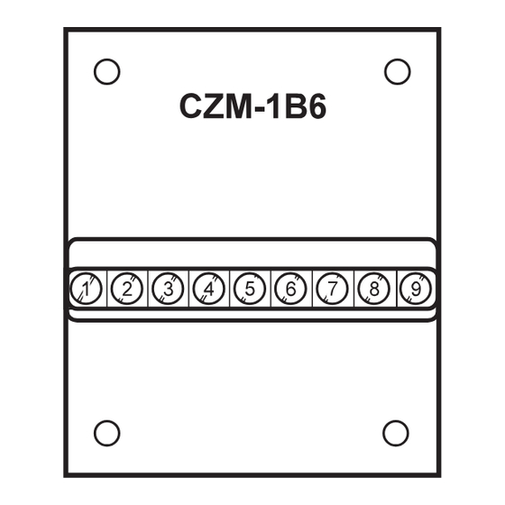
Figure 1
Model CZM-1B6
Siemens Building Technologies, Ltd.
Fire Safety & Security Products
2 Kenview Boulevard
Brampton, Ontario
L6T 5E4 Canada
Advertisement
Table of Contents

Related Manuals for Siemens CZM-1B6


Summary of Contents for Siemens CZM-1B6
- Page 1 2-wire, ionization or photoelectric smoke detectors. Electrical Connections It can also monitor an unlimited number of shorting After you have set the CZM-1B6 address, connect the devices such as waterflow switches, thermal field wiring. There are three basic connections to the detectors, manual stations, etc.
- Page 2 CZM-1B6 in this configuration. The devices in the tables at the right are listed for use with the CZM-1B6. Use up to fifteen detectors, any combination of those listed. Only one PB-1191 or one DF-1192, and no additional devices, can be connected to a CZM-1B6.
- Page 3 PSR-1 on terminals 3-6. The power may be wired as shows both wiring types, as well as the connections to Class A or Class B. Since the CZM-1B6 monitors the either the MMB or the MOM-4 when the ALD-2I power at its screw terminals, you can star or T-tap the module is used.
- Page 4 3½ inches. i t c 2. When the field wiring is connected (See above), press the CZM-1B6 into the box and fasten it with the four screws provided. 3. Attach a dress bezel if necessary, making sure Zone resistance:...
Need help?
Do you have a question about the CZM-1B6 and is the answer not in the manual?
Questions and answers