Table of Contents
Advertisement
Quick Links
Installation and maintenance instructions
CFL-WRG Comfort slimline ventilation unit
(Translation of the original)
CFL 32
CFL 10 / 15 / 22
WOLF GMBH / P.O. BOX 1380 / D-84048 MAINBURG / TEL. +49 (0)87 51 74-0 / FAX +49 (0)87 51 74-16 00 / www.WOLF.eu
Document no.: 3065065_201704
Subject to modifications
GB
IE
Advertisement
Table of Contents

Related Manuals for Wolf CFL-WRG


Summary of Contents for Wolf CFL-WRG
- Page 1 (Translation of the original) CFL 32 CFL 10 / 15 / 22 WOLF GMBH / P.O. BOX 1380 / D-84048 MAINBURG / TEL. +49 (0)87 51 74-0 / FAX +49 (0)87 51 74-16 00 / www.WOLF.eu Document no.: 3065065_201704 Subject to modifications...
-
Page 2: Table Of Contents
Table of contents Contents ....................Page 1. General information / reference symbols............ 3 2. Safety instructions ..................4 3. Standards and regulations...............5-6 4. Unit layout....................7-8 5. Specification ....................9 6. Delivery / handling ..................10 7. Installation / siting ................11-14 Installation location ................11 Louver dampers .................. -
Page 3: General Information / Reference Symbols
1. General information / reference symbols General information These maintenance instructions are only applicable to Wolf CFL-WRG ventilation units. Authorised personnel should read these instructions before any commissioning or maintenance work. Adhere to the specifications in this document. Installation, commissioning and maintenance work must only be carried out by trained personnel. -
Page 4: Safety Instructions
Any faults or damage that impact or might impact on the safety or correct function of the unit must be remedied immediately by qualified personnel. Replace faulty components and equipment only with original WOLF spare parts. The unit may only be used for handling air. This air must not contain... -
Page 5: Standards And Regulations
Intended use Wolf CFL-WRG compact ventilation units are designed to heat and filter normal air. Use of these units in rooms with explosive atmospheres is not permissible. Handling very dusty or corrosive media is not permissible. Air intake temperatures from -20 °C to +40 °C... - Page 6 3. Standards and regulations Standards and regulations The following standards and regulations apply to the ventilation units: - Machinery Directive 2006/42/EC - Low Voltage Directive 2014/35/EU - EMC Directive 2014/30/EU - ErP Directive 2009/125/EC - EN ISO 12100 Safety of machinery; general design principles - EN ISO 13857 Safety of machinery; safety distances - EN 349 Safety of machinery;...
-
Page 7: Unit Layout
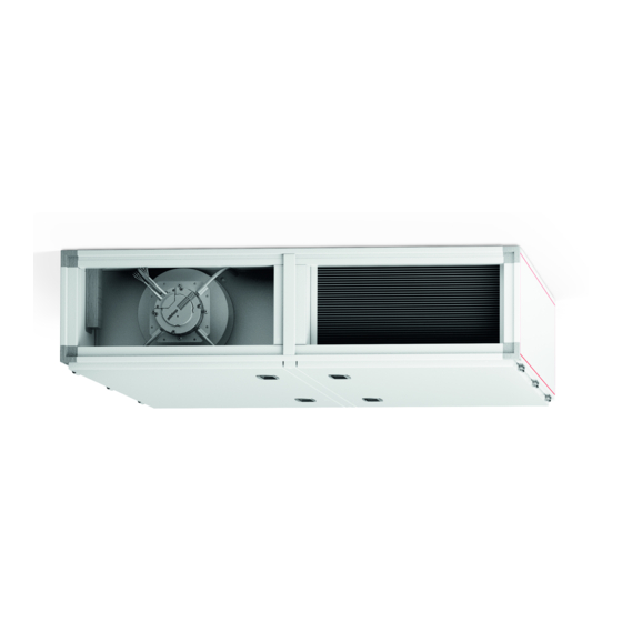
4. Unit layout CFL-WRG Comfort slimline ventilation unit (CFL 10 / 15 / 22) Operating side, supply air right / supply air left = mirror inverted EC fan, supply air Supply air Extract air M5 compact filter, extract air Differential pressure switch, extract air filter Control unit Countercurrent plate heat exchanger and condensate pan Inspection door Bypass damper with servomotor (variable speed) F7 compact filter, outdoor air... -
Page 8: Unit Layout
4. Unit layout CFL-WRG Comfort slimline ventilation unit (CFL 32) Operating side, supply air right / supply air left = mirror inverted Supply air Extract air M5 compact filter, extract air Inspection door Differential pressure switch, extract air filter Countercurrent heat exchanger EC fan, supply air Control unit Inspection door Bypass Pan panel Bypass damper with servomotor (variable speed) -
Page 9: Specification
5. Specification Specification Size 10-WRG 15-WRG 22-WRG 32-WRG Max. air volume m³/h 1000 1500 2200 3200 at available ext. pressure, supply air at available ext. pressure, extract air Heat recovery rate > 90 > 90 > 90 > 90 Height A mm Width B mm 1017... -
Page 10: Delivery / Handling
If there is any damage or even a suspicion of damage, the recipient must indicate this on the consignment note and have it countersigned by the haulier. The recipient of the goods must notify Wolf of the relevant facts without delay. Dispose of the transport packaging in accordance with local regulations. -
Page 11: Installation / Siting
7. Installation / siting CFL-WRG installation location The CFL-WRG is designed as an indoor unit and intended solely for ceiling installation. The ceiling where the unit will be mounted must be level and sufficiently load bearing (min. 500 kg/m²). Only install the unit with the standard suspension brackets supplied, as shown in the illustration. -
Page 12: Louver Dampers
7. Installation / siting Louver dampers Always fit the louver dampers as shown in the illustration. CFL 10 / 15 / 22 / 32 Servomotors Secure servomotors with the supplied mounting bracket, as shown in the CFL 10 / 15 / 22 / 32 illustration. -
Page 13: Trap
7. Installation / siting Trap The effective trap head h (mm) must be greater than the maximum under- or overpressure at the condensate connector (1 mmWC = 10 Pa). h = 1.5 x p (mmWC) + 50 mm (min.) = Under- or overpressure in mmWC acc. to appliance design 50 mm (WC) = Reserve (inaccuracy in design, evaporation) = Additional safety factor Do not connect the trap drain line directly to the public sewage system. -
Page 14: Hydraulic Connection
7. Installation / siting Hydraulic connection Heating coil: H ydraulic Admixing circuit connection example Benefits: good control characteristics, low risk of freezing ϑ1 =ϑ2 Diverting circuit Cooling coil: H ydraulic Benefits: constant flow connection example temperature in cooling coil, good dehumidification even at partial load Note: Positioning valves close to the heat exchanger improves the control characteristics Air connection Operating side, supply air left... -
Page 15: Electrical Connection
There is no personal safety protection if the unit is operated with RCDs. Regularly check that all electrical equipment is working correctly. Observe the specified electrical MCB/fuse protection ratings. We accept no liability for any damage or loss resulting from technical modifications to Wolf control units. 3065065_201704... -
Page 16: Electrical Connection
8. Electrical connection Image: CFL 10 / 15 / 22 Entry for on-site cables Image: CFL 32 Entry for on-site cables Open bypass inspection door Remove cover plate from control unit and connect cables according to wiring diagrams. Check cover plate for leak tightness when installing. -
Page 17: Commissioning
The unit must not be operated before all necessary safety equipment has been fitted and connected. Intake and discharge apertures must be connected to ensure contact protection. The CFL-WRG unit must be level and safely secured. Commissioning must be carried out by authorised personnel (Wolf Customer Service). - Page 18 - To modify functions and parameters, see the installation and operating instructions provided. Where the system is not commissioned by Wolf, check all inputs and outputs for correct wiring and function: - Frost protection function - Fan rotational direction...
- Page 19 Recomm. min. air flow rate CFL-10 300 m³/h CFL-15 600 m³/h CFL-22 800 m³/h CFL-32 1400 m³/h Filter monitoring Before commissioning the CFL-WRG, set the differential pressure switches on the outdoor air and extract air filters to a value of 200 Pa (scale dial). 3065065_201704...
- Page 20 9. Commissioning Countercurrent plate heat The countercurrent plate heat exchanger is generally maintenance-free. exchanger / bypass damper During commissioning, check whether the servomotor for the bypass damper is rotating in the correct direction (bypass/HR mode). Condensate pan Provide a trap for the condensate drain and route the condensate into the sewerage system.
- Page 21 9. Commissioning Flow rate calculation The flow rate is calculated using the effective pressure method. This involves comparing the static pressure upstream of the inlet nozzle with the static pressure in the inlet nozzle. The flow rate can be calculated from effective pressure Δp (differential pressure of the two static pressures) using the following equation.
- Page 22 9. Commissioning CFL 22 effective pressure For the CFL 22 use a K value of 131. Flow rate [m³/h] Δp = effective pressure Δp [Pa] (symbolic representation) [m³/h] 1000 1200 1400 1600 1800 2000 2200 CFL 32 effective pressure For the CFL 32 use a K value of 162. Flow rate [m³/h] Δp = effective pressure Δp...
-
Page 23: Maintenance Shutdown
10. Maintenance shutdown Before starting any maintenance work, switch OFF the mains isolator and safeguard against unauthorised reconnection. If the isolator is switched back on unintentionally, maintenance staff or others in the vicinity could be at risk from rotating parts. Wait for the fans to come to a complete standstill before opening the doors (approx. 2 minutes). Also observe the clearly visible warning on the unit. -
Page 24: Hygiene Checklist
Heating coil: Check for contamination, Clean and repair damage, corrosion and tightness Check condensate pan for contamination, Clean and repair corrosion, damage and tightness Check the function of the drain and trap Clean and repair Repairs Only qualified personnel may remove faults or repair damage. Only replace faulty components with original Wolf spare parts. 3065065_201704... -
Page 25: Maintenance Instructions
12. Maintenance instructions Electrical equipment - Regularly check the electrical equipment of the unit. - Replace loose connections and faulty cables immediately. - Regularly check the earth conductor. Servomotors on the dampers The motors are maintenance-free. At regular intervals, check that the connection from the servomotor to the damper drive is firmly seated. - Page 26 12. Maintenance instructions CFL 10 / 15 / 22 1. Disconnect trap drain connection 2. Open inspection doors 3. Undo unit partition screws and remove partition 4. Remove seals (sealant) from condensate pan and condensate drain 5. Undo condensate pan threaded connection 6.
- Page 27 12. Maintenance instructions CFL 32 2 persons are required for removing the pan panel. 1. Disconnect trap drain connection 2. Open bypass inspection door 3. Remove pan panel connecting screws (3x) 4. Undo screws at side of pan panel and remove pan panel 5.
- Page 28 12. Maintenance instructions Fan motor unit Motor and bearing are maintenance-free. If necessary, clean the impeller with a soapy solution. Check that the test lead (if fitted) is seated firmly at the test connector on the Please inlet nozzle. note Loose seating can result in faulty measurements. The integral installation aid facilitates removal of the complete fan/motor unit with front plate.
- Page 29 12. Maintenance instructions Bypass servomotor The motors are maintenance-free. At regular intervals, check that the connection from the servomotor to the bypass is firmly seated. CFL 10 / 15 / 22 CFL 32 Condensate pan Regularly check the condensate pan for possible soiling and clean if required (see checklist).
-
Page 30: Spare Parts List
2980940 Servomotor for bypass damper CM24-SR-F10-R-WLF 2269611 Pluggable temperature sensor 2799058 Inspection door partition 6217979 CFL-WRG inspection door, operating side, supply air right 6217981 CFL-WRG inspection door, operating side, supply air left 6218904 CFL 15 - WRG Pos. Designation Comments Mat. no. - Page 31 W406 x H842 x D48 1669202 Differential pressure switch JDL-112 2738360 Countercurrent plate heat exchanger GS 45 / 520 2981955 Servomotor for bypass damper CM24-SR-F10-R-WLF 2269611 Pluggable temperature sensor 2799058 Inspection door partition 6219303 CFL-WRG inspection door 6219285 CFL-WRG inspection door, bypass 6219290 3065065_201704...
- Page 32 Wolf GmbH P.O. Box 1380 / D-84048 Mainburg / Tel. +49 (0)87 51 74-0 Fax +49 (0)87 51 74-16 00 www.wolf.eu Document no.: 3065065_201704 Subject to modifications...
Need help?
Do you have a question about the CFL-WRG and is the answer not in the manual?
Questions and answers