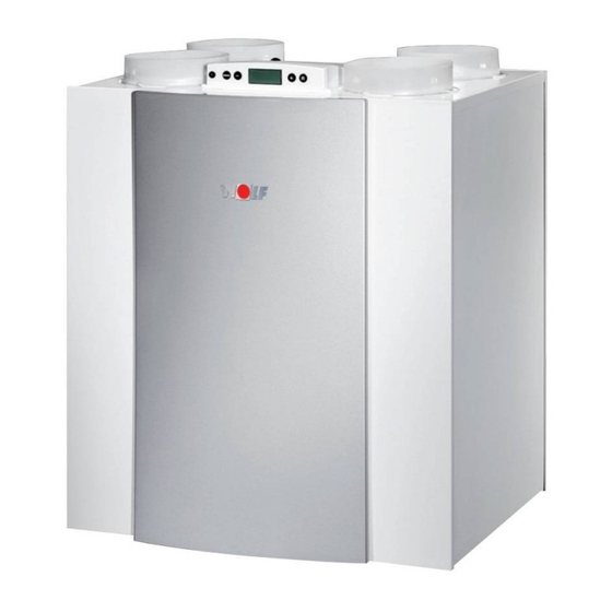
Advertisement
Quick Links
Advertisement

Summarization of Contents
1. Delivery
1.1 Scope of delivery
Lists the components included with the heat recovery unit for installation and initial setup.
3. Version
3.1 Technical information CWL-300 Excellent
Provides detailed technical specifications for the CWL-300 Excellent model.
3.2 Fan graph CWL-300 Excellent
Illustrates fan performance curves for the CWL-300 Excellent model.
3.3 Technical information CWL-400 Excellent
Provides detailed technical specifications for the CWL-400 Excellent model.
3.4 Fan graph CWL-400 Excellent
Illustrates fan performance curves for the CWL-400 Excellent model.
3.5 Connections and dimensions
Details the physical layout and connection points for CWL-300/400 Excellent models.
3.5.1 CWL-300/400 Excellent, right-handed version
Details the physical layout and connection points for right-handed models.
3.5.2 CWL-300/400 Excellent, left-handed version
Details the physical layout and connection points for left-handed models.
3.6 Exploded view appliance
Provides a detailed breakdown of the appliance's components with numbering for identification.
4. Operation
4.1 Description
Explains the automatic plug-and-play functionality and heat recovery process.
4.2 Bypass conditions
Details the conditions under which the bypass valve automatically opens and closes.
4.3 Frost protection
Describes the intelligent frost protection system and its function during cold conditions.
4.4 Version
Outlines connection options for various applications using connectors X14 and X15.
5. Installation
5.1 Installation general
General guidelines and regulatory requirements for installing the appliance.
5.2 Placing the appliance
Instructions on how and where to mount the appliance securely and level.
5.3 Connecting the condensate discharge
Details on connecting the condensate drainpipe and creating an air trap.
5.4 Connecting ducts
Guidance on connecting air supply and extract ducts, including insulation and acoustic considerations.
5.4 Connecting ducts
Further instructions on duct routing, condensation prevention, and resistance limits.
5.5 Electric connections
Essential for powering and controlling the unit.
5.5.1 Connecting the power plug
Instructions for connecting the appliance to the mains power supply safely.
5.5.2 Connecting the multiple switch
Details on connecting a multiple switch for control and filter indication.
5.5.3 Connecting eBus connector
Instructions for connecting the eBus connector for appliance coupling and control.
6. Display
6.1 General explanation control panel
Overview of the LCD display, control keys, and basic interface functions.
6.2 Operating mode
Explains the different elements displayed during operation, including fan status and air flow.
6.2.1 Status System fan
Details how fan status is indicated on the display, including numbers for different situations.
6.2.2 Display air flow rate
Explains how the air flow rate is shown on the display and what it signifies.
6.2.3 Message text for operating mode
Lists and explains various message texts that can appear on the display during operation.
6.3 Settings menu
Guides on how to access and modify settings for optimal appliance performance.
6.4 Readout menu
Instructions on how to view current sensor values and appliance performance data.
6.5 Service menu
Explains how to access the service menu to view recent fault messages and codes.
7. Putting into operation
7.1 Switching the appliance on and off
Provides methods for turning the appliance on and off via software and power plug.
7.2 Setting the air flow rate
Details how to set different air flow rates and their dependencies on system conditions.
7.3 Other settings installer
Mentions that other settings can be modified, referring to the settings menu.
7.4 Factory setting
Instructions on how to reset all modified settings back to the original factory configuration.
8. Fault
8.1 Trouble shooting
General guidance on identifying and resolving faults indicated by spanner symbols and fault codes.
8.2 Display codes
Explains the meaning of non-locking and locking faults shown on the display.
Fault Code Table
Lists various fault codes, their causes, and the recommended actions for the appliance and installer.
9. Maintenance
9.1 Filter cleaning
Step-by-step guide on how to clean or replace the unit's filters and reset the indicator.
9.2 Maintenance
Instructions for installer maintenance, including cleaning the heat exchanger and fans.
10. Elektric diagrams
10.1 Basic diagram
Provides a schematic overview of the appliance's electrical connections and components.
10.2 Wiring diagram
Illustrates the detailed wiring connections between various components of the appliance.
11. Elektric connections accessoires
11.1 Connectors
Details the different connectors (X1, X2, X14, X15) and their functions for accessory connections.
11.2 Connection examples multiple switch
Shows various examples of how to connect multiple switches and remote controls.
11.3 Couple CWL-300/400 Excellent through eBus contact
Explains how to connect multiple CWL units via eBus for synchronized operation and air flow control.
11.4 Wiring diagram postheater connection or extra preheater
Provides wiring diagrams for connecting postheaters or extra preheaters to the unit.
11.5 Connection example geo heat exchanger
Details the connection of a geo heat exchanger to the appliance for enhanced thermal management.
11.6 Connecting external switch contact
Instructions for connecting external switch contacts for controlling fan operation and bypass.
11.7 Connection to 0-10 V input
Explains how to connect external sensors (e.g., humidity, CO2) using 0-10V inputs for control.
11.8 Connection RH (huminity) - sensor
Details the connection of a humidity sensor for automatic humidity regulation within the dwelling.
12. Service
12.1 Exploded view
Visual breakdown of the appliance components with part numbers for service and replacement.
12.2 Notes
Provides important notes regarding replacement parts and safety during maintenance.
13. Setting values
Setting Values Table
Comprehensive list of adjustable parameters, their factory settings, and ranges for optimal operation.


Need help?
Do you have a question about the CWL-400 Exxellent and is the answer not in the manual?
Questions and answers