Advertisement
Quick Links
Advertisement

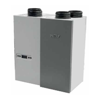
Summary of Contents for Wolf CWL-180 Excellent
-
Page 1: Installation Instructions
Installation Instructions HEAT-RECOVERY-UNIT CWL - 180 Excellent... - Page 2 ......................................................................... 10.1 ..................................11.1 ........11.2 ........11.2.1 ....11.2.2 3.3.1 ..............3.3.2 ..11.2.3 ....................11.2.4 ................................11.3 ................................ 11.4 11.5 .............
- Page 3 Art. No.: 30 63 650...
- Page 4 Art. No.: 30 63 650...
- Page 5 Art. No.: 30 63 650...
- Page 6 Art. No.: 30 63 650...
- Page 7 Art. No.: 30 63 650...
- Page 8 CWL-180 Excellent IP30 Ø 125 Ø 20 1.48 In practice, the value may deviate 1 dB(A) as a result of measuring tolerances Note: The value stated in the circle is the capacity per fan (in Watt) Art. No.: 30 63 650...
- Page 9 Art. No.: 30 63 650...
- Page 10 11 12 13 14 15 16 17 Connections top appliance Art. No.: 30 63 650...
- Page 11 9-pole Art. No.: 30 63 650...
- Page 12 Art. No.: 30 63 650...
- Page 13 1 = CWL-180 Excellent left-handed 4/0 (install level) 2 = Preferred ventilation air supply 3 = Ventilation air supply under the tiles 4a = Free suction bottom roof area 4b = Free suction top roof area 5 = Sewage system vent stack 6 = Preferred location exhaust ventila- tion air;...
- Page 14 Make allowance for a 1000 W preheater/postheater that may optionally be connected. Filter Timer control BML Excellent (eBus): Week programme Art. No.: 30 63 650...
- Page 15 A = display B = 4 control keys Art. No.: 30 63 650...
- Page 16 Art. No.: 30 63 650...
- Page 17 Master - appliance Slave - appliance Art. No.: 30 63 650...
- Page 18 Settings menu is active Do not Set value Step number set value Back to operating mode Art. No.: 30 63 650...
- Page 19 readout value Step no. readout value; refer to the table below for an explanation operating mode settings menu operating mode readout menu Art. No.: 30 63 650...
- Page 20 operating mode settings menu service menu operating mode Fault code; for fault code explanation see §8.1 and § 8.2 fault message no. Art. No.: 30 63 650...
- Page 21 Art. No.: 30 63 650...
- Page 22 press > 10 sec. simultaneously 3 sec. displayed operating mode Art. No.: 30 63 650...
- Page 23 E999 Correct settings dip Correct settings dip switches switches CWL-180 CWL-180 Excellent with Excellent extension kit Art. No.: 30 63 650...
- Page 24 E108 E111 E999 Art. No.: 30 63 650...
- Page 25 ‘-’ “R Art. No.: 30 63 650...
- Page 26 ‘-’ Art. No.: 30 63 650...
- Page 27 Art. No.: 30 63 650...
- Page 28 1 2 3 4 5 6 7 8 1 2 3 4 5 6 7 8 1 2 3 4 1 2 3 4 1 2 3 1 2 3 4 Q P O N A = Multiple switch M = Postheater (optional) B = Preheater (optional) N = Output 0-10 V (optional) C = Outdoor temperature sensor...
- Page 29 1 & 2 3 & 4 5 & 6 7 & 8 Art. No.: 30 63 650...
- Page 30 Excellent Excellent B = Receiver for wireless remote control C = Transmitter with 4 settings (for instance the kitchen) D = Any additional 4-settings transmitters (A maximum of 6 transmitters can be logged on to 1 receiver) Excellent Excellent C = Receiver for wireless remote control D = Transmitter with 2 settings C = Splitter E = Splitter...
- Page 31 = Multiple switch = 2-Pole connector = CWL-180 Excellent (Master) C1 - C* = CWL-180 Excellent (Slave) CWL-180 set as “Master”. A = CWL-180 Excellent B = Control board; to access board, see 9.2 item 1 - 5...
- Page 32 II = II = III = III = IV = Art. No.: 30 63 650...
- Page 33 A = Minimum temperature B = Maximum temperature I = To dwelling II = To atmosphere III = From dwelling IV = From atmosphere ON = OFF = Art. No.: 30 63 650...
- Page 34 A = CWL-180 Excellent with extension kit B = 9-pole connector C = Contact connected to switch input 1; for instance a switch or a relay contact D = Display CWL -180 Excellent (text “CN1” appears when contact C is closed.) m³/h...
- Page 35 A = CWL-180 Excellent with extension kit B = 9-pole connector C = Provision connected to 0-10 V input; for instance a humidity sensor or a CO sensor. Connected provision has its own power sup- ply. D = Display CWL-180 Excellent Excellent with extension kit (text “V2”...
- Page 36 Art. No.: 30 63 650...
- Page 37 1668492 2138034 2745155 2745156 2070707 2745159 2745401 Art. No.: 30 63 650...
- Page 38 BYPASS BYPASS BUSADR contact R, page 28) contact R, page 28) contact R, page 28) contact R, page 28) contact R, page 28) Art. No.: 30 63 650...
- Page 39 contact R, page 28) contact R, page 28) contact R, page 28) contact R, page 28) contact R, page 28) contact R, page 28) contact R, page 28) Art. No.: 30 63 650...
- Page 40 Wolf GmbH CWL 180 Excellent 4277 4305 4362 4475 6528 6571 6657 6830 2251 2266 2296 2355 * Measurements executed by TZWL according to the DIBT-standards (TZWL-report M.94.10.01.095.AA.0409, Octobre 2007) Art. No.: 30 63 650...
- Page 41 Art. No.: 30 63 650...
- Page 42 Nr.: Wolf GmbH Art. No.: 30 63 650...


Need help?
Do you have a question about the CWL-180 Excellent and is the answer not in the manual?
Questions and answers