Advertisement
Table of Contents
- 1 Table of Contents
- 2 Parts List
- 3 Installation to Wood Stud Wall
- 4 Installation to Metal Stud Wall
- 5 Installation to Solid Concrete and Cinder Block Wall
- 6 Attaching Adapter Brackets to Screen
- 7 Attaching Mounting Bracket Using Hook on Option
- 8 Attaching Mounting Bracket Using Tilt Option
- Download this manual
Advertisement
Table of Contents

Related Manuals for peerless-AV HT642-004


Summary of Contents for peerless-AV HT642-004
- Page 1 Installation and Assembly: Tilt Wall Mount with Component Storage Capability Model: HT642-004 Max Load Capacity: 80 lb (29 kg) ISSUED: 09-21-11 SHEET #: 125-9245-1...
-
Page 2: Table Of Contents
Note: Read entire instruction sheet before you start installation and assembly. WARNING • Do not begin to install your Peerless product until you have read and understood the instructions and warnings contained in this Installation Sheet. If you have any questions regarding any of the instructions or warnings, please call Peerless customer service at 1-800-729-0307. • This product should only be installed by a qualified professional. • Make sure that the supporting surface will safely support the combined load of the equipment and all attached hard- ware and components. •... -
Page 3: Parts List
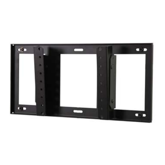
Before you start make sure all parts listed are included with your product. PARTS LIST Description Qty. Part # A right adapter bracket 201-1943 B left adapter bracket 201-1942 C wall plate 201-1940 D M4 x 12 mm socket serrated washer head screw 510-1079 E M6 x 16 mm socket pin screw 520-1132... -
Page 4: Installation To Wood Stud Wall
Installation to Wood Stud Walls WARNING • Installer must verify that the supporting surface will safely support the combined load of the equipment and all attached hardware and components. • Tighten wood screws so that wall plate is firmly attached, but do not overtighten. Overtightening can damage the screws, greatly reducing their holding power. • Never tighten in excess of 80 in. • lb (9 N.M.). • Make sure that mounting screws are anchored into the center of the stud. The use of an "edge to edge" stud finder is highly recommended. • Hardware provided is for attachment of mount through standard thickness drywall or plaster into wood studs. Install- ers are responsible to provide hardware for other types of mounting situations. Use a stud finder to locate the edges of the stud. Use of an edge-to-edge stud finder is highly recommended. -
Page 5: Installation To Metal Stud Wall
Installation to Metal Stud Walls STUD FOR METAL STUD WALLS ONLY: Drill four 1/2" (13mm) dia. holes through drywall and studs at lo- cations corresponding to wall plate. Insert togglers (F) as shown below... Skip to Step 2 page 7 WARNING • Product must be mounted through drywall that has a minimum thickness of 1/2" and into metal studs, 26 gauge or heavier. • Make sure that togglers are anchored into the center of the studs as shown in figure 1. The use of an "edge to edge" stud finder is highly recommended. fig. 1 Pivot end of toggler (F). -
Page 6: Installation To Solid Concrete And Cinder Block Wall
Installation to Solid Concrete or Cinder Block WARNING • When installing Peerless wall mounts on cinder block, verify that you have a minimum of 1-3/8" (35 mm) of actual concrete thickness in the hole to be used for the concrete anchors. Do not drill into mortar joints! Be sure to mount in a solid part of the block, generally 1" (25 mm) minimum from the side of the block. Cinder block must meet ASTM C-90 specifications. It is suggested that a standard electric drill on slow setting is used to drill the hole instead of a hammer drill to avoid breaking out the back of the hole when entering a void or cavity. • Concrete must be 2000 psi density minimum. Lighter density concrete may not hold concrete anchor. - Page 7 Attaching Adapter Brackets to Display 7.87" (200mm) DETAIL 1 .98" (25mm) 7.87" (200mm) BACK OF DISPLAY Attaching Adapter Brackets using VESA 200 x 100 Mounting Pattern Using information provided in detail 1 secure adapter brackets (A and B) to back of display using four M4 x 12 mm socket pin screws (D), with #8 washers (C) using 18" long 4 mm allen wrench (G) as shown below.
-
Page 8: Attaching Adapter Brackets To Screen
Attaching Adapter Brackets using VESA 200 x 200 Mounting Pattern Using information provided in detail 1 secure two adapter brackets (A and B) to back of display with four M6 x 16 mm socket pin screws (E) and nylon shoulder washers (O), or four M8 x 10 mm socket pin screws (N) using 18" long 4 mm allen wrench (G). -
Page 9: Attaching Mounting Bracket Using Hook On Option
Attaching Mounting Bracket Using Hook On Option Attach four M5 x 12 mm serrated washer head Position slots of adapter plates (A and B) onto the socket pin screws (J) to the holes on the sides of four M5 x 12 mm serrated washer head socket pin wall plate (C) using the 4mm security allen screws (J) attached to wall plate (C). -
Page 10: Attaching Mounting Bracket Using Tilt Option
Attaching Mounting Bracket Using Tilt Option Attach two M5 x 12 mm serrated washer head Position slots of adapter brackets (A and B) onto socket pin screws (J) to the bottom holes on the the two M5 x 12 mm serrated washer head socket sides of wall plate (C) using the 4mm security allen pin screws (J) attached to wall plate (C).
Need help?
Do you have a question about the HT642-004 and is the answer not in the manual?
Questions and answers