Advertisement
Installation Instructions
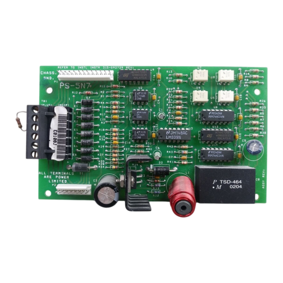
Model PS-5N7
Network Interface / 5V Power Supply
OPERATION
The Model PS-5N7 from Siemens Building
Technologies, Inc. permits remote mounting
of the MXL annunciator modules MKB-1,
MKB-2, and RCC-1/-1F. In addition, when the
PS-5N7 is used with a PIM-1, it provides an
interface for a remote printer that can be
supervised or unsupervised. Each PS-5N7
occupies one network node.
INSTALLATION
Mounting
The PS-5N7 can be used in an MME-3, MSE-2,
or an RCC-1/-1F enclosure. Mount the PS-5N7
in the following enclosures as described below
(See the Note at the top of page 2 if using a
PIM-1):
PS-5N7 Wiring Diagram in MME-3 or MSE-2 (Without a PIM-1)
Siemens Building Technologies, Inc.
8 Fernwood Road
Florham Park, New Jersey 07932
P/N 315-092729-13
1. MME-3—Install in the upper right-hand
corner (See Figure 1).
2. MSE-2—Install in the upper right-hand
corner (See Figure 1).
3. RCC-1/-1F—Install in the lower right-
hand corner (See Figure 2).
Note: In a special application which is
described on page 7, the PS-5N7
can be used as a source of
power in a remote extender
enclosure used to house extra
VSMs/VLMs/VFMs.
Figure 1
Siemens Building Technologies, Ltd.
2 Kenview Boulevard
Brampton, Ontario L6T 5E4 CN
Fire Safety
Advertisement
Table of Contents

Subscribe to Our Youtube Channel
Related Manuals for Siemens PS-5N7


Summary of Contents for Siemens PS-5N7
-
Page 1: Installation Instructions
(See the Note at the top of page 2 if using a PIM-1): Figure 1 PS-5N7 Wiring Diagram in MME-3 or MSE-2 (Without a PIM-1) Siemens Building Technologies, Inc. Siemens Building Technologies, Ltd. 8 Fernwood Road... - Page 2 Figure 2 PS-5N7 Wiring Diagram in the RCC-1/-1F Enclosure (Without a PIM-1) Four male/female standoffs are provided in When using a PIM-1 with the PS-5N7 in each backbox in the correct location for an MME-3 or MSE-2 backbox (See Figure 3): installing the PS-5N7.
-
Page 3: Power Connection
Figure 4 PS-5N7 Cabling Diagram in the RCC-1/-1F Enclosure (With a PIM-1) Using PS-5N7 with Style 7 When using a PIM-1 Module with the (4- Wire) Network Connections PS-5N7 in an RCC-1/-1F Enclosure (See Figures 4 and 5): Do not place the PS-5N7 module in the last position on a Style 7 Network. -
Page 4: Electrical Connections
TB2, 18, 19 Notes: 1. Use a minimum wire gauge of 18 AWG. 6. DO NOT place the PS-5N7 at the end of the network (Style 7 only). 2. Use a maximum of 80 ohms per pair of wires for the network connections. -
Page 5: Electrical Ratings
24 VDC supply lines. i t c The following power supplies are compat- ible with the PS-5N7. They are listed with their maximum output current (I PSR-1 amps PLM-35 1.5 amps... - Page 6 There are multiple MXLs that are not networked. In order to add Voice hardware to a remote enclosure, use a PS-5N7 module to drive an Adding a PS-5N7 and an OMM-1 under OMM-1 if the following conditions apply: these conditions provides power as well as communication with the MXLV.
- Page 7 To Use the PS-5N7 Module in a Remote Extender Enclosure: Refer to Wiring Specification for MXL, MXL-IQ and MXLV Systems, P/N 315-092772 revision 6 or higher, for additional wiring information. For additional information on this configuration, refer to the following Installation Instructions:...
- Page 8 Siemens Building Technologies, Inc. Siemens Building Technologies, Ltd. 8 Fernwood Road 2 Kenview Boulevard Florham Park, New Jersey 07932 Brampton, Ontario L6T 5E4 CN P/N 315-092729-13...
Need help?
Do you have a question about the PS-5N7 and is the answer not in the manual?
Questions and answers