Sign In
Upload
Download
Table of Contents
Contents
Add to my manuals
Delete from my manuals
Share
URL of this page:
HTML Link:
Bookmark this page
Add
Manual will be automatically added to "My Manuals"
Print this page
×
Bookmark added
×
Added to my manuals
Manuals
Brands
Cisco Manuals
Server
APIC M3
Installation and service manual
Cisco APIC M3 Installation And Service Manual
Hide thumbs
1
2
Table Of Contents
3
4
5
6
7
8
9
10
11
12
13
14
15
16
17
18
19
20
21
22
23
24
25
26
27
28
29
30
31
32
33
34
35
36
37
38
39
40
41
42
43
44
45
46
47
48
49
50
51
52
53
54
55
56
57
58
59
60
61
62
63
64
65
66
67
68
69
70
71
72
73
74
75
76
77
78
79
80
81
82
83
84
85
86
87
88
89
90
91
92
93
94
95
96
97
98
99
100
101
102
103
104
105
106
107
108
109
110
111
112
113
114
115
116
117
118
119
120
121
122
123
124
125
126
127
128
129
130
page
of
130
Go
/
130
Contents
Table of Contents
Bookmarks
Table of Contents
Table of Contents
CHAPTER 1 Overview
External Features
Serviceable Component Locations
Summary of Server Features
CHAPTER 2 Installing the Server
Installation Warnings and Guidelines
Grounding Requirements
Rack Requirements
Installing the Server in a Rack
Installing the Cable Management Arm (Optional)
Reversing the Cable Management Arm (Optional)
Initial Server Setup
Connecting to the Server Locally for Setup
Connecting to the Server Remotely for Setup
Setting up the System with the Cisco IMC Configuration Utility
NIC Mode and NIC Redundancy Settings
Updating the BIOS and Cisco IMC Firmware
Accessing the System BIOS
Smart Access Serial
Smart Access USB
Front-Panel Leds
Chapter 3
Maintaining the Server
Rear-Panel Leds
Internal Diagnostic Leds
Preparing for Component Installation
Required Equipment for Service Procedures
Shutting down and Removing Power from the Server
Shutting down Using the Power Button
Shutting down Using the Cisco IMC CLI
Shutting down Using the Cisco IMC GUI
Removing the Server Top Cover
Serial Number Location
Hot Swap Vs Hot Plug
Removing and Replacing Components
Serviceable Component Locations
Replacing SAS/SATA Hard Drives or Solid State Drives
4K Sector Format SAS/SATA Drives Considerations
SAS/SATA Drive Population Guidelines
Replacing a SAS/SATA Drive
Replacing a Front-Loading Nvme SSD
Front-Loading Nvme SSD Population Guidelines
Enabling Hot-Plug Support in the System BIOS
Front-Loading NVME SSD Requirements and Restrictions
Replacing a Front-Loading Nvme SSD
Installing a Pcie Cable for Front-Loading Nvme Ssds
Replacing HHHL Form-Factor Nvme Solid State Drives
HHHL Form-Factor NVME SSD Requirements and Restrictions
HHHL SSD Population Guidelines
Replacing an HHHL Form-Factor Nvme SSD
Replacing Fan Modules
Replacing Memory Dimms
DIMM Population Rules and Memory Performance Guidelines
Replacing Dimms
Replacing Cpus and Heatsinks
CPU Configuration Rules
Tools Required for CPU Replacement
Replacing a CPU and Heatsink
Additional CPU-Related Parts to Order with RMA Replacement Cpus
Additional CPU-Related Parts to Order with RMA Replacement System Chassis
Moving an M5 Generation CPU
Replacing a Mini-Storage Module
Replacing a Mini-Storage Module Carrier
Replacing an SD Card in a Mini-Storage Carrier for SD
Replacing a Micro SD Card
Replacing an M.2 SSD in a Mini-Storage Carrier for M.2
Replacing a USB Drive
Replacing an Internal USB Drive
Enabling or Disabling the Internal USB Port
Replacing the RTC Battery
Replacing AC Power Supplies
Replacing Power Supplies
Pcie Slot Specifications
Replacing a Pcie Card
Replacing a Pcie Card
Cisco Virtual Interface Card (VIC) Considerations
Replacing an Mlom Card
Replacing an Mraid Riser (Riser 3)
Replacing a SAS Storage Controller Card (RAID or HBA)
Storage Controller Card Firmware Compatibility
Replacing a SAS Storage Controller Card (RAID or HBA)
Replacing the Supercap (RAID Backup)
Replacing a SATA Interposer Card
Replacing a Chassis Intrusion Switch
Installing a Trusted Platform Module (TPM)
TPM Considerations
Installing and Enabling a TPM
Service Headers and Jumpers
Using the BIOS Recovery Header (J38, Pins 11 - 12)
Using the Clear CMOS Header (J38, Pins 9 - 10)
Procedure 1: Reboot with Recovery.cap File
Procedure 2: Use BIOS Recovery Header and Bios.cap Recovery File
Using the Clear Password Header (J38, Pins 13 - 14)
Using the Boot Alternate Cisco IMC Image Header (J39, Pins 1 - 2)
Using the Reset Cisco IMC Password to Default Header (J39, Pins 3 - 4)
Using the Reset Cisco IMC to Defaults Header (J39, Pins 5 - 6)
Appendix A Server Specifications
Server Specifications
Physical Specifications
Environmental Specifications
Power Specifications
770 W AC Power Supply
1050 W DC Power Supply
Power Cord Specifications
Storage Controller Considerations
Supported Storage Controllers and Cables
This Appendix Provides Storage Controller (RAID and HBA) Information.
Storage Controller Card Firmware Compatibility
Write-Cache Policy for Cisco 12G SAS Modular RAID Controller
Mixing Drive Types in RAID Groups
RAID Controller Migration
Storage Controller and Backplane Connectors
Embedded SATA RAID Controller
Embbeded SATA RAID Requirements
Embedded SATA RAID Controller Considerations
Embedded SATA RAID: Two SATA Controllers
Enabling SATA Mode for the Embedded Controllers
Accessing the Software RAID Configuration Utility
Installing LSI Megasr Drivers for Windows and Linux
Downloading the Megasr Drivers
Microsoft Windows Server Drivers
Linux Drivers
For more RAID Utility Information
GPU Card Installation
Server Firmware Requirements
GPU Card Configuration Rules
Requirement for All Gpus: Memory-Mapped I/O Greater than 4 GB
Replacing a Single-Wide GPU Card
Installing Drivers to Support the GPU Cards
Updating the Server BIOS
Updating the GPU Card Drivers
Installation for Cisco UCS Manager Integration
Advertisement
Quick Links
1
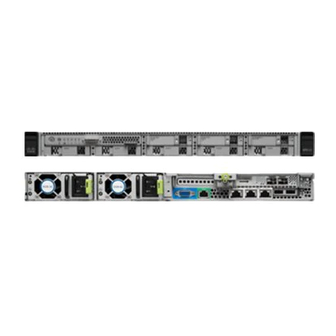
External Features
Download this manual
Cisco APIC M3/L3 Server Installation and Service Guide
First Published: 2018-10-25
Americas Headquarters
Cisco Systems, Inc.
170 West Tasman Drive
San Jose, CA 95134-1706
USA
http://www.cisco.com
Tel: 408 526-4000
800 553-NETS (6387)
Fax: 408 527-0883
Table of
Contents
Previous
Page
Next
Page
1
2
3
4
5
Advertisement
Table of Contents
Need help?
Do you have a question about the APIC M3 and is the answer not in the manual?
Ask a question
Questions and answers
Related Manuals for Cisco APIC M3
Server Cisco MCS-7825-H1-IPC1 Installation Manual
Installation guide (54 pages)
Server Cisco TelePresence MSE 8710 Installation Manual
(12 pages)
Server Cisco TelePresence 7010 Help Manual
Telepresence server 7010 and mse 8710 in remotely managed mode (92 pages)
Server Cisco TelePresence 7010 Help Manual
Telepresence server 7010 and mse 8710 in locally managed mode (132 pages)
Server Cisco Meraki MX65 Installation Manual
(5 pages)
Server Cisco 7835-H2 - Media Convergence Server Datasheet
Highly available server platform (9 pages)
Server Cisco 700 MHz Installation And Upgrade Manual
Audio server (134 pages)
Server Cisco MXE 3500 Hardware Installation Manual
Media experience engine (6 pages)
Server Cisco TelePresence Server 7010 Product User Manual
(151 pages)
Server Cisco MCS-78 Series Error Code List
Media convergence server (13 pages)
Server Cisco Firepower Management Centers Instructions Manual
Memory upgrade (20 pages)
Server Cisco Firepower Management Center 750 Getting Started Manual
Firepower management center (42 pages)
Server Cisco Cisco MeetingPlace Express Troubleshooting Manual
(20 pages)
Server Cisco MSE 3365 Installation Manual
(10 pages)
Server Cisco UCS E Series Hardware Installation Manual
Servers and network compute engine (62 pages)
Server Cisco APIC M4 Installation And Service Manual
(46 pages)
This manual is also suitable for:
Apic l3
Table of Contents
Save PDF
Print
Rename the bookmark
Delete bookmark?
Delete from my manuals?
Login
Sign In
OR
Sign in with Facebook
Sign in with Google
Upload manual
Upload from disk
Upload from URL


Need help?
Do you have a question about the APIC M3 and is the answer not in the manual?
Questions and answers