Table of Contents
Advertisement
Quick Links
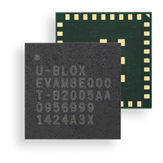
EVA-M8E
u-blox M8 Miniature Untethered Dead Reckoning
Module
Hardware Integration Manual
Abstract
This document describes the hardware features and specifications of the ultra-compact EVA-M8E
UDR module featuring the u-blox M8 positioning engine. The EVA M8E offers flexibility in the
selection and placement of an external Inertial Measurement Unit and Flash memory and achieves
Dead Reckoning performance without requiring speed information from the target vehicle. The EVA-
M8E module combines exceptional UDR and GNSS performance with highly flexible power, design,
and serial communication options.
www.u-blox.com
UBX-15028542 - R05
Advertisement
Table of Contents

Subscribe to Our Youtube Channel
Related Manuals for u-blox EVA-M8E


Summary of Contents for u-blox EVA-M8E
- Page 1 This document describes the hardware features and specifications of the ultra-compact EVA-M8E UDR module featuring the u-blox M8 positioning engine. The EVA M8E offers flexibility in the selection and placement of an external Inertial Measurement Unit and Flash memory and achieves Dead Reckoning performance without requiring speed information from the target vehicle.
-
Page 2: Document Information
The information contained herein is provided “as is” and u-blox assumes no liability for its use. No warranty, either express or implied, is given, including but not limited to, with respect to the accuracy, correctness, reliability and fitness for a particular purpose of the information. -
Page 3: Table Of Contents
2.8.2 Schematic design-in for EVA-M8E ....................18 2.9 Pin description ............................19 2.10 Layout design-in checklist ........................20 2.11 Layout ................................20 2.11.1 Footprint .............................21 2.11.2 Paste mask ............................21 2.11.3 Placement ............................21 2.12 C93-M8E Application Board- Evaluating EVA-M8E Module ............22 UBX-15028542 - R05 Page 3 of 44 Production Information... - Page 4 EVA-M8E - Hardware Integration Manual 2.13 EOS/ESD/EMI precautions ........................22 2.13.1 Electrostatic Discharge (ESD) .......................22 2.13.2 ESD protection measures .......................22 2.13.3 Electrical Overstress (EOS) ......................23 2.13.4 EOS protection measures .......................23 2.13.5 Applications with cellular modules ....................23 Untethered Dead Reckoning ......................25 3.1 Implementation ............................25 3.2 Installation ..............................25...
- Page 5 EVA-M8E - Hardware Integration Manual B.6 External LNA (U1) .............................39 B.7 Mandatory SQI Flash (U3) ........................40 B.8 Mandatory External Sensor Modules (U4) ...................40 B.9 RF ESD protection diode (D2) .........................40 B.10 Operational amplifier (U6) ........................40 B.11 Open-drain buffer (U7, U8 and U9) ......................40 B.12 LDO Voltage Regulator (U10) .........................40...
-
Page 6: Hardware Description
EVA form factor. EVA offers the designer flexibility in the selection and placement of peripheral components: EVA-M8E only requires Flash memory, an inertial sensor, and an optional real- time clock (RTC) crystal. The EVA-M8E’s sensor may be installed in any stable position within the vehicle without configuration. -
Page 7: Design-In
The different supply voltages are explained in the following subsections. Figure 1 shows an example to supply the EVA-M8E module when not using the USB interface. In this case, the VDD_USB pin is connected to ground. -
Page 8: Power Management Configuration
2.1.1.2 I/O supply voltage (VCC_IO) The digital I/Os of the EVA-M8E module can be supplied with a separate voltage from the host system connected to the VCC_IO pin of the module. The wide range of VCC_IO allows seamless interfacing to standard logic voltage levels. -
Page 9: Interfaces
Single supply voltage for VCC and VCC_IO, use of a backup supply see Appendix, Figure 17 ☞ For description of the different power operating modes, see the EVA-M8E Data Sheet [1]. 2.2 Interfaces The EVA-M8E module provides UART, SPI, DDC (I C compliant) interfaces for communication with a host CPU. -
Page 10: Display Data Channel (Ddc) Interface
For a detailed list of supported sensor modules, see Appendix B.8. 2.2.5 USB interface The USB interface of the EVA-M8E module supports the full-speed data rate of 12 Mbit/s. It is compatible to the USB 2.0 FS standard. The interface requires some external components in order to implement the physical characteristics required by the USB 2.0 specification. -
Page 11: Sqi Flash Memory
The voltage level of the SQI interface follows the VCC_IO level. Therefore, the SQI Flash must be supplied with the same voltage as VCC_IO of the EVA-M8E. It is recommended to place a decoupling capacitor (C4) close to the supply pin of the SQI Flash. -
Page 12: I/O Pins
EVA-M8E modules have a configurable VCC_IO monitor threshold (iomonCfg) to ensure that the EVA-M8E receiver only starts if the VCC_IO supply is within the supply range of the SQI Flash device (VCC_IO is used to supply the SQI Flash). This will ensure that any connected SQI Flash memory will be detected correctly at startup. -
Page 13: Time Pulse
Pin PIO14/ANT_DET can be used as an optional external interrupt pin with fixed input voltage thresholds with respect to VCC_IO (see the EVA-M8E Data Sheet [1] for more information).It can be used for force-OFF the receiver or aiding.. By default, the external interrupt is disabled. -
Page 14: Electromagnetic Interference And I/O Lines
The status of the active antenna can be checked by the UBX-MON-HW message. More information see the u-blox 8 / u-blox M8 Receiver Description Including Protocol Specification [2]. The open drain buffers U4, U7 and U8 (e.g. Fairchild NC7WZ07) are needed to shift the voltage levels. -
Page 15: Real-Time Clock (Rtc)
B.1. 2.4.3 Time aiding Time can also be sent by UBX message at every startup of the EVA-M8E module. This can be done to enable warm starts, AssistNow Autonomous and AssistNow Offline. This can be done when no RTC is maintained. -
Page 16: Rf Input
If a passive antenna is connected to the EVA-M8E module, it is recommended to use an additional LNA in front of EVA-M8E. An LNA (U1) alone would make the EVA-M8E module more sensitive to out- band jammers, so an additional GNSS SAW filter (F1) has to be connected between the external LNA (U1) and the EVA-M8E module’s RF-input If strong out-band jammers are close to the GNSS antenna... -
Page 17: Improved Jamming Immunity
USB in Safe Boot Mode. For communication by UART in Safe Boot Mode, a training sequence (0x 55 55 at 9600 baud) can be sent by the host to the EVA-M8E in order to enable communication. After sending the training sequence, the host has to wait for at least 2 ms before u-blox 8 / u-blox M8 sending messages to the EVA-M8E receiver. -
Page 18: Design-In Checklist
The total noise figure including external LNA (or the LNA in the active antenna) should be around 1 dB. With the EVA-M8E module, an external LNA is mandatory if no active antenna is used to achieve the performance values as written in the EVA-M8E Data Sheet [1]. ... -
Page 19: Pin Description
EVA-M8E - Hardware Integration Manual 2.9 Pin description Pin # Name Description Remark RF_IN RF Input Add external LNA and SAW if no active antenna used. Ground Outer ground pin Reserved Reserved Do not connect. Must be left open! Reserved Reserved Do not connect. -
Page 20: Layout Design-In Checklist
Is the grounding concept optimal? Has the 50 Ohm line from antenna to EVA-M8E (micro strip / coplanar waveguide) been kept as short as possible? Assure low serial resistance in VCC power supply line (choose a line width > 400 um). -
Page 21: Footprint
EVA-M8E - Hardware Integration Manual 2.11.1 Footprint Pin36 Pin1 Figure 5: Recommended footprint (bottom view)- units are in mm 2.11.2 Paste mask The paste mask shall be 50 µm smaller than the copper pads with a paste thickness of 100 µm. -
Page 22: C93-M8E Application Board- Evaluating Eva-M8E Module
EVA-M8E - Hardware Integration Manual 2.12 C93-M8E Application Board- Evaluating EVA-M8E Module Based on the EVA-M8E module, the C93-M8E application board enables immediate evaluation of u- blox’s Untethered Dead Reckoning technology in most vehicle applications. The C93-M8E includes antenna, RTC and peripheral components required to complete an end-product design in a small case, ready for mounting in a vehicle application. -
Page 23: Electrical Overstress (Eos)
☞ See the GPS Implementation and Aiding Features in u-blox wireless modules [5]. 2.13.5.1 Isolation between GNSS and GSM antenna In a handheld type design, an isolation of approximately 20 dB can be reached with careful placement of the antennas. - Page 24 EVA-M8E - Hardware Integration Manual GPS Carrier Pow er [dBm] 1575.4 M Hz Interference signal signals Jammin g signal GPS input filter GPS input filter -110 characteristics characteristics Frequency [M Hz] 1525 1525 1550 1550 1575 1575 1600 1600 1625...
-
Page 25: Untethered Dead Reckoning
EVA-M8E - Hardware Integration Manual Untethered Dead Reckoning 3.1 Implementation The EVA-M8E 3D Untethered Dead Reckoning module makes use of GNSS and external 3D gyroscope and 3D accelerometer sensors only with no need or provision for speed pulse or forward/reverse information. -
Page 26: Product Handling & Soldering
4.1 Packaging, shipping, storage and moisture preconditioning For information pertaining to reels and tapes, Moisture Sensitivity levels (MSD), shipment and storage information, as well as drying for preconditioning see the EVA-M8E Data Sheet [1]. 4.2 ESD handling precautions ESD prevention is based on establishing an Electrostatic Protective Area (EPA). The EPA can be a small working station or a large manufacturing area. -
Page 27: Reflow Soldering
☞ EVA-M8E must not be soldered with a damp heat process. 4.3.3 Optical inspection After soldering the EVA-M8E module, consider an optical inspection step to check whether: • The module is properly aligned and centered over the pads 4.3.4 Repeated reflow soldering Only single reflow soldering processes is recommended for boards populated with EVA-M8E module. -
Page 28: Use Of Ultrasonic Processes
EVA-M8E - Hardware Integration Manual 4.3.8 Use of ultrasonic processes Some components on the EVA-M8E module are sensitive to Ultrasonic Waves. Use of any Ultrasonic Processes (cleaning, welding etc.) may cause damage to the GNSS Receiver. ☞ u-blox offers no warranty against damages to the EVA-M8E module caused by any Ultrasonic Processes. -
Page 29: Product Testing
Product testing 5.1 Test parameters for OEM manufacturer Because of the testing done by u-blox, it is obvious that an OEM manufacturer doesn’t need to repeat firmware tests or measurements of the GNSS parameters/characteristics (e.g. TTFF) in their production test. -
Page 30: Appendix
EVA-M8E - Hardware Integration Manual Appendix A Reference schematics A.1 Cost optimized circuit • Passive Antenna • No RTC crystal • No backup battery • UART and DDC for communication to host Figure 14: Cost optimized circuit UBX-15028542 - R05... -
Page 31: Best Performance Circuit With Passive Antenna
EVA-M8E - Hardware Integration Manual A.2 Best performance circuit with passive antenna • External LNA • RTC crystal • Backup battery • UART and DDC for communication to host Figure 15: Best performance circuit UBX-15028542 - R05 Appendix Page 31 of 44... -
Page 32: Improved Jamming Immunity With Passive Antenna
EVA-M8E - Hardware Integration Manual A.3 Improved jamming immunity with passive antenna • External SAW filter – LNA – SAW filter • RTC crystal • Backup battery • UART and DDC for communication to host Figure 16: Standard circuit for an improved jamming immunity... -
Page 33: Circuit Using Active Antenna
EVA-M8E - Hardware Integration Manual A.4 Circuit using active antenna • Active antenna • RTC crystal • Backup battery • UART and DDC for communication to host Figure 17: Standard circuit using active antenna UBX-15028542 - R05 Appendix Page 33 of 44... -
Page 34: Usb Self-Powered Circuit With Passive Antenna
EVA-M8E - Hardware Integration Manual A.5 USB self-powered circuit with passive antenna • External LNA • RTC crystal • Backup battery • UART and DDC for communication to host • USB interface Figure 18: USB self-powered circuit UBX-15028542 - R05... -
Page 35: Usb Bus-Powered Circuit With Passive Antenna
EVA-M8E - Hardware Integration Manual A.6 USB bus-powered circuit with passive antenna • External LNA • RTC crystal • Backup battery • SPI for communication to host • USB interface Figure 19: USB bus-powered circuit UBX-15028542 - R05 Appendix Page 35 of 44... -
Page 36: Circuit Using 2-Pin Antenna Supervisor
EVA-M8E - Hardware Integration Manual A.7 Circuit using 2-pin antenna supervisor • 2-pin antenna supervisor • RTC crystal • Backup battery • UART and DDC for communication to host Figure 20: Circuit using 2-pin antenna supervisor UBX-15028542 - R05 Appendix... -
Page 37: Circuit Using 3-Pin Antenna Supervisor
EVA-M8E - Hardware Integration Manual A.8 Circuit using 3-pin antenna supervisor • 3-pin antenna supervisor • RTC crystal • Backup battery • UART and DDC for communication to host Figure 21: Circuit using 3-pin antenna supervisor UBX-15028542 - R05 Appendix... -
Page 38: B Component Selection
EVA-M8E - Hardware Integration Manual B Component selection This section provides information about components that are critical for the performance of the EVA- M8E GNSS receiver module. Recommended parts are selected on a data sheet basis only. Temperature range specifications need only be as wide as required by a particular application. For the purpose of this document, specifications for industrial temperature range (-40 C …... -
Page 39: External Lna Protection Filter (F2)
EVA-M8E - Hardware Integration Manual B.3 External LNA protection filter (F2) Depending on the application circuit, consult manufacturer data sheet for DC, ESD and RF power ratings! Manufacturer Order No. System supported Comments TDK/ EPCOS B8401: B39162-B8401- GPS+GLONASS High attenuation... -
Page 40: Mandatory Sqi Flash (U3)
EVA-M8E - Hardware Integration Manual Table 14: Recommend parts list for external LNA B.7 Mandatory SQI Flash (U3) Manufacturer Order No. Comments Macronix MX25L3233F 3V, 32Mbit, several package/temperature options Macronix MX25V8035F 3V, 8Mbit, several package/temperature options Macronix MX25R1635FxxxH1 3V, 16Mbit, several package/temperature options... -
Page 41: Antenna Supervisor Switch Transistor (T1)
EVA-M8E - Hardware Integration Manual B.13 Antenna supervisor switch transistor (T1) Manufacturer Order No. Vishay Si1016X-T1-E3 (p-channel) Table 21: Recommend parts list for antenna supervisor switch transistor (p-channel MOSFET) B.14 Ferrite beads (FB1) Manufacturer Order No. Comments MuRata BLM15HD102SN1 High impedance @ 1.575 GHz... -
Page 42: Standard Resistors
EVA-M8E - Hardware Integration Manual B.18 Standard resistors Name Type / Value USB data serial termination 27R 5% 0.1W USB data serial termination 27R 5% 0.1W Pull-up at antenna supervisor transistor 100K 5% 0.1W Antenna supervisor current limiter 10R 5% 0.25W Antenna supervisor voltage divider 560R 5% 0.1W... -
Page 43: Related Documents
GPS Compendium, Docu. No. GPS-X-02007 GPS Implementation and Aiding Features in u-blox wireless modules, Docu. No. GSM.G1-CS- 09007 ☞ For regular updates to u-blox documentation and to receive product change notifications, register on our homepage (www.u-blox.com). Revision history Revision Date... -
Page 44: Contact
EVA-M8E - Hardware Integration Manual Contact For complete contact information, visit us at www.u-blox.com. u-blox Offices North, Central and South America Headquarters Asia, Australia, Pacific Europe, Middle East, Africa u-blox America, Inc. u-blox Singapore Pte. Ltd. u-blox AG Phone: +1 703 483 3180...
Need help?
Do you have a question about the EVA-M8E and is the answer not in the manual?
Questions and answers