Table of Contents
Advertisement
Quick Links
Advertisement
Table of Contents

Related Manuals for Garmin GPSmap 585 Plus


Summary of Contents for Garmin GPSmap 585 Plus
- Page 1 Owner's Manual...
- Page 2 © 2017 Garmin Ltd. or its subsidiaries All rights reserved. Under the copyright laws, this manual may not be copied, in whole or in part, without the written consent of Garmin. Garmin reserves the right to change or improve its products and to make changes in the content of this manual without obligation to notify any person or organization of such changes or improvements.
-
Page 3: Table Of Contents
Data Fields ....................8 Selecting the Transducer Type ............... 3 Zooming In and Out of the Chart ............3 Sonar ...................8 Panning on the GPSMAP 585 Plus ............3 Full Screen Sonar ................... 8 Adjusting the Backlight................3 Garmin ClearVü Sonar View..............9 Changing the Color Mode ............... - Page 4 Setting the Scroll Speed ................18 Chart Appearance Settings ................27 Sonar Appearance Settings ................18 Fish Eye 3D Settings ..................28 Advanced Sonar Settings ................19 Garmin Quickdraw™ Contours Mapping ............28 Interference....................20 Accessing the Garmin Quickdraw Community ..........31 Surface Noise ....................20 GPSMAP 585 Plus ®...
- Page 5 Sharing Your Garmin Quickdraw Contours Maps with the Garmin Quickdraw Editing a Saved Route ................35 Community ....................31 Viewing a List of Routes ............... 35 Downloading Garmin Quickdraw Community Maps ........32 Browsing for and Navigating a Saved Route ........36 Deleting a Saved Route ................
- Page 6 Lunar Calendar ..................47 DSC List ....................44 Device Configuration ............47 Viewing the DSC List ..................44 GPSMAP 585 Plus Settings Menu Tree ..........47 Adding a DSC Contact ..................44 Incoming Distress Calls ................ 44 System Settings ..................49 Navigating to a Vessel in Distress ..............44 System Information ..................49...
- Page 7 Restoring the Factory Default Settings ..........54 Appendix ................55 Registering Your Device ............... 55 Sun Cover ..................... 55 GPSMAP 585 Plus Specifications ............55 Troubleshooting ..................56 My device does not turn on................56 My sonar does not work ................56 My device is not creating waypoints in the correct location ......57 物質宣言...
- Page 8 GPSMAP 585 Plus ®...
-
Page 9: Introduction
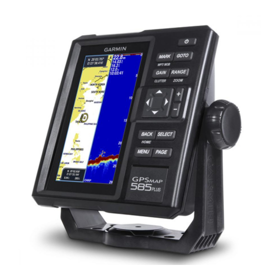
Introduction Device Overview WARNING See the Important Safety and Product Information guide in the product box for product warnings and other important information. GPSMAP 585 Plus Dimensions 176 mm 66.8 mm Power key Device keys SD card slot Connector Descriptions... -
Page 10: Keys
From a 2D chart or sonar page, select MENU, and hold MARK/WPT routes, and tracks to another compatible Garmin chartplotter or a computer. to mark your boat position as a waypoint. -
Page 11: Software Update
Before you can update the software, you must obtain a software-update memory card or load the latest software onto a memory card. Panning on the GPSMAP 585 Plus 1 Turn on the chartplotter. You can move the chart to view an area other than your present location. -
Page 12: Changing The Color Mode
2 Adjust the backlight. 2 Select an option: • To use a light background, select Day Colors. Changing the Color Mode • To use a dark background, select Night Colors. 1 Select Settings > System > Display > Color Mode. TIP: You can configure the night color mode. -
Page 13: Setting The Beeper
Customizing the Home Screen over on the screen. You can add items to and rearrange items on the Home screen. For more information about GPS, go to www.garmin.com/aboutGPS. 1 From the Home screen, select Customize Home. 2 Select an option: Home Screen •... -
Page 14: Adding A New Layout To The Home Screen
Page Shortcuts Adding a New Layout to the Home Screen You can create a custom screen to suit your needs, which is added to your You can quickly open commonly used pages by selecting PAGE from any home screen. page. 1 Select Customize Home >... -
Page 15: Editing The Page Shortcuts
To customize the Trip screen, select Trip > MENU. Speed Data Graph Reset Trip: Resets the trip data and allows you to record new trip data. GPSMAP 585 Plus Navigation Chart Reset Odometer: Resets the odometer data and allows you to record new odometer data. -
Page 16: Adding The Depth Data Graph Page
Sonar Adding the Depth Data Graph Page Before you can customize the Depth Data Graph page, you must add it to the Full Screen Sonar home screen. From the home screen, select Customize Home > Add > Sonar > Depth You can see a full-view graph of sonar readings from a transducer on the full Data Graph. -
Page 17: Garmin Clearvü Sonar View
Bottom echo Water temperature GPS speed Garmin ClearVü Sonar View Device voltage NOTE: To receive Garmin ClearVü scanning sonar, you need a compatible Time transducer. Suspended targets (fish) Garmin ClearVü high-frequency scanning sonar provides a detailed picture of the fishing environment around the boat in a detailed representation of Depth line structures the boat is passing over. -
Page 18: Traditional 50/77/200 Khz Sonar
ClearVü Scanning Sonar The Garmin ClearVü scanning sonar technology takes one step further by emitting two narrow beams with CHIRP technology, similar to the shape of the beam in a copying machine. -
Page 19: Split-Screen Frequency
Shift-Zoom View On the sonar screen, you can see a full-view graph of sonar readings on the right side of the screen, and a magnified portion of that graph on the left side of the screen. Shift allows you to set the depth range on which the sonar is focused. This allows you to zoom in a higher resolution in the focused depth. -
Page 20: Adjusting The Zoom
Adjusting the Zoom Bottom Lock You can lock the screen to the water bottom. For example, if you select a You can adjust the zoom manually by specifying the span and a fixed starting span of 20 meters, the device shows an area from the water bottom to 20 depth. -
Page 21: Shift Zoom
Shift Zoom Adjust the zoom range This is a unique sonar zoom technology from Garmin. It displays the selected depth and range of sonar to fill the left-side of the screen in more accuracy and detail. In the Shift Zoom mode the fishfinder CPU only processes the sonar signals received from the selected depth range. -
Page 22: Reducing The Clutter
Reducing the Clutter Creating a Mark or Waypoint on a Sonar Screen Using Your Present Location You can quickly change the settings to reduce noise and clutter on the sonar screen. 1 Pause the sonar. 1 From a sonar view, hold GAIN/CLUTTER to open the Clutter Menu. 2 Select an option: •... -
Page 23: Selecting Frequencies
search and judging the bottom conditions. NOTE: You cannot adjust the frequency for all sonar views and transducers. You can indicate which frequencies appear on the sonar screen. Higher frequencies results in better resolutions, and are thus more useful for 1 From a sonar view, select MENU >... -
Page 24: Sonar Gain
Sonar Gain Setting the Gain Automatically NOTE: To set the gain on the split-frequency screen, you must set each The Gain control function amplifies the signal received from the sonar frequency separately. returning echoes. The signal strength from the echoes is stronger in shallow water than in deeper water due to the lesser distance the echo has to travel 1 From a sonar view, select GAIN. -
Page 25: Setting The Gain Manually
Setting the Gain Manually 1 From a sonar screen, select RANGE. 1 From a sonar screen, select GAIN. 2 Select an option: 2 Select until you begin to see noise in the water portion of the • To allow the device to adjust the range automatically based on the screen. -
Page 26: Setting The Scroll Speed
NOTE: Showing a depth line on one screen displays the depth line on all the The Auto setting selects a scroll rate to match the boat speed, so screens. targets in the water are drawn with the correct aspect ratio and appear less distorted. -
Page 27: Advanced Sonar Settings
Color Scheme: Sets the color scheme. Shows suspended targets as symbols. Edge: Highlights the strongest signal from the bottom to help define the Shows suspended targets as symbols with target depth information. hardness or softness of the signal. A-Scope: Displays a vertical flasher along the right side of the screen that Shows suspended targets as symbols with background sonar information. -
Page 28: Interference
Interference 1. Sonar Cross-Talk interference: caused by nearby fishfinder(s) of similar transmit frequency. It will appear as the diagonal lines across the screen. Adjusts the sensitivity to reduce the effects of interference from nearby When two fishfinder’s transducer cones intersect, the units will not be able sources of noise. -
Page 29: Color Gain
Color Gain Adjusts the appearance of returns to compensate for weakened sonar signals in deeper water, and reduces the appearance of noise near the surface. Adjusts the intensity of colors shown on the screen. When the value of this setting is increased, the colors associated with low- You can adjust the Color Gain to change the sonar signal strength threshold level noise and fish targets appear more consistent through various water for the strongest colors on your sonar screen. -
Page 30: Compass
Compass Graph or Temperature Data Graph The compass uses GPS course over ground (COG) to guide you to your destination, and does not account for other factors that can affect your destination, such as currents and tides. Select Navigation Info > Compass. Charts and 3D Chart Views The charts and 3D chart views that are available depend on the map data and accessories used. -
Page 31: Navigation Chart And Offshore Fishing Chart
Mariner’s Eye 3D: Shows a detailed, three-dimensional view from above and behind the boat (according to your course) and provides a visual navigation aid. This view is helpful when navigating tricky shoals, reefs, bridges, or channels, and when trying to identify entry and exit routes in unfamiliar harbors or anchorages. -
Page 32: Viewing Location And Object Information On A Chart
aids and symbols, obstructions, and cable areas. NOTE: Auto Guidance is available with premium charts, in some areas. 1 From the Navigation chart or Fishing chart, select a location. Viewing Location and Object Information on a Chart 2 If necessary, select SELECT. You can select GOTO You can view information about a location or an object on the Navigation 3 Select Navigate To. -
Page 33: Chart And 3D Chart Settings
Chart and 3D Chart Settings Marks, Waypoints, and Tracks on the Charts and Chart Views From a chart or a 3D chart view, select MENU > Marks, Waypoints, & NOTE: Not all settings apply to all charts and 3D chart views. Some options Tracks. -
Page 34: Navigation And Fishing Chart Setup
DSC Trails: Shows the tracks of DSC vessels, and selects the length of the appears using a trail. track that appears using a trail. Vessel Outline: Shows the outline of AIS vessels. AIS Alarm: Sets the safe-zone collision alarm (page 30). Navigation and Fishing Chart Setup AIS Display Setup NOTE: Not all settings apply to all charts and 3D chart views. -
Page 35: Showing A Navigation Inset
5 Select a data field. 6 Select the type of data shown in the field. Available data options vary based on the chartplotter and network configuration. Showing a Navigation Inset You can control whether a navigation inset appears on some chart views. The navigation inset is shown only when the boat is navigating to a destination. -
Page 36: Fish Eye 3D Settings
WARNING These differences are visible only when zoomed out too far to see the The Garmin Quickdraw Contours mapping feature allows users to generate detailed charts. maps. Garmin makes no representations about the accuracy, reliability, Spot Depths: Turns on spot soundings and sets a dangerous depth. Spot completeness or timeliness of the maps generated by third parties. - Page 37 16 and 32 km/h (10 and 20 mph). A red circle indicates poor depth or GPS position, and a speed above 32 km/h (20 mph). You can view Garmin Quickdraw Contours in a combination screen or as a single view on the map.
- Page 38 1 Select the SD memory card slot in Active Card to record the Qucikdraw shows your own Garmin Quickdraw Contours maps. The Community mapping data. Contours option shows maps you downloaded from the Garmin Quickdraw 2 Select Name to change the Quickdraw map’s file name. Community.
-
Page 39: Accessing The Garmin Quickdraw Community
Adding a Label to a Garmin Quickdraw Contours Map others in the Garmin Quickdraw Community. You can add labels to a Garmin Quickdraw Contours map to mark hazards or When you share a contour map, only the contour map is shared. Your points of interest. -
Page 40: Downloading Garmin Quickdraw Community Maps
Downloading Garmin Quickdraw Community Maps and include the waypoint name and symbol. You can download Garmin Quickdraw Contours maps that other users have Marks are locations you record without navigation information. Marks display created and shared with the Garmin Quickdraw Community. -
Page 41: Creating A Waypoint On A Sonar Screen Using A Different Location
Creating a Waypoint on a Sonar Screen Using a • To change the depth, select Depth. Different Location • To change the water temperature, select Water Temp.. • To change the comment, select Comment. 1 Select to pause the sonar. •... -
Page 42: Deleting All Waypoints
Deleting All Waypoints Routes & Auto Guidance Paths: Shows the list of routes. Proximity Waypoint: Shows the list of particular locations within a specified Select User Data > Manage Data > Clear User Data > Waypoints > All. range. Copying Waypoints, Routes, and Tracks to a Memory Boundaries: Shows the list of marked legal, safety, or geographical boundaries. -
Page 43: Creating And Navigating A Route Using The Waypoint Map
5 Select an option. Creating and Navigating a Route Using the Waypoint List 1 Select User Data > Routes & Auto Guidance Paths > New > Route Using Waypoint List. 2 Select waypoints. 3 Select BACK > Navigate To. Editing a Saved Route You can change the name of a route or change the turns the route contains. -
Page 44: Browsing For And Navigating A Saved Route
Browsing for and Navigating a Saved Route Deleting All Saved Routes Select User Data > Manage Data > Clear User Data > Routes & Auto Before you can browse a list of routes and navigate to one of them, you must create and save at least one route. -
Page 45: Deleting All Saved Waypoints, Routes, And Tracks
resolution interval is recommended for the most efficient use of memory. 1 Select User Data > Tracks > Active Track Options > Record Interval > Interval. 2 Select an option: • To record the track based on a distance between points, select Distance >... -
Page 46: Marking A Waypoint On The Ais Radar Screen
Marking a Waypoint on the AIS Radar Screen Customizing the Display of the AIS Radar Screen 1 From the AIS Radar screen, use the arrow keys to select a location. You can configure how other vessels appear on the AIS Radar screen. 2 Select MARK. -
Page 47: Setting The Safe-Zone Collision Alarm
AIS emergency device, you must enable the chartplotter to receive test alerts. 3 Select Range. 1 From the AIS Radar screen, select MENU > AIS Alarm. 4 Select a distance for the safe-zone radius around your vessel. 5 Select Time To. 6 Select a time at which the alarm will sound if a target is determined to intersect the safe zone. -
Page 48: Measuring The Range And Bearing To A Target Object
1 From the AIS Radar screen, select MENU > Adjust VRM/EBL > Move Heading Line: Shows an extension from the bow of the boat in the direction VRM/ EBL. of travel on the AIS Radar screen. 2 Use the arrow keys to adjust the VRM and EBL. Range Rings: Shows the range rings that help you to visualize distances on the AIS Radar screen. -
Page 49: Showing And Customizing The Highway Overlay Numbers
4 Select an overlay box. Mark or waypoint 5 Select the data to show. Distance to destination 6 Select BACK. Track line Coordinates Auto Guidance Distance off course CAUTION The Auto Guidance feature is based on electronic chart information. That Showing and Customizing the Highway Overlay data does not ensure obstacle and bottom clearance. -
Page 50: Auto Guidance Path Configurations
during navigation. the appropriate distance from shore, you can assess the placement of the Auto Guidance path using one or more familiar destinations that require Auto Guidance Path Configurations navigation through a narrow waterway (page 33). CAUTION Adjusting the Distance from Shore The Preferred Depth and Safe Height settings influence how the chartplotter CAUTION calculates an Auto Guidance path. - Page 51 • If the Auto Guidance line is too close to known obstacles, select Distance setting. Settings > Navigation > Auto Guidance > Shoreline Distance > Far. • If the turns in the Auto Guidance line are too wide, select Settings > Navigation >...
-
Page 52: Digital Selective Calling
Digital Selective Calling 1 Select Navigation Info > Other Vessels > DSC List > Add Contact. 2 Enter the Maritime Mobile Service Identity (MMSI) of the vessel. Networked Chartplotter and VHF Radio Functionality 3 Enter the name of the vessel. If you have a NMEA 0183 VHF radio connected to your chartplotter, these Incoming Distress Calls features are enabled. -
Page 53: Navigating To A Tracked Vessel
Individual Routine Calls 1 Select Navigation Info > Other Vessels > DSC List. When you connect the chartplotter to a Garmin VHF radio, you can use the chartplotter interface to set up an individual routine call. 2 Select a position-report call. -
Page 54: Making An Individual Routine Call
5 Select Send. The chartplotter sends information about the call to the radio. 6 On your Garmin VHF radio, select Call. Making an Individual Routine Call to an AIS Target 1 From a chart or 3D chart view, select an AIS target. -
Page 55: Lunar Calendar
。 Factory Settings 。 Simulator • My Vessel � Keel Offset 。 Temp. Offset Device Configuration 。 Calibrate Water Speed GPSMAP 585 Plus Settings Menu Tree • Communications � Serial Port • System � Display 。 NMEA 0183 Setup 。 Backlight �... - Page 56 。 Route 。 Fish 。 System 。 Off 。 Garmin 。 。 Posn Precision 。 。 XTE Precision 。 。 Waypoint IDs 。 AIS 。 MMSI 。 AIS Alarm 。 Diagnostics 。 Time To 。 Defaults 。 Range 。 AIS-EPIRB Test •...
-
Page 57: System Settings
Software Information: Provides information about the device and the software version. Garmin Devices: Provides information about connected Garmin devices. Factory Settings: Restores the device to factory settings. NOTE: This deletes any setting information you have entered. -
Page 58: Setting The Keel Offset
NOTE: A buffer of 2 to 3 feet from the bottom of the keel is recommended to ensure a safe distance from the keel to the bottom. 1 Complete an action, based on the location of the transducer: • If the transducer is installed at the water line , measure the distance from the transducer location to the keel of the boat. -
Page 59: Setting The Water Temperature Offset
5 If the wheel turns freely, check the cable connections. You can set the temperature offset to compensate for the temperature reading from a temperature-capable sensor. 6 If you continue to get the message, contact Garmin product support. 1 Measure the water temperature using the temperature-capable transducer Alarms Settings that is connected to the device. -
Page 60: System Alarms
System Alarms Select Settings > Alarms > System. Shallow Water: Sounds when the water depth is shallower than the specified depth. Deep Water: Sounds when the water depth is deeper than the specified depth. Alarm Clock: Sets an alarm clock. Water Temp.: Sounds when the water temperature varies more than ±... -
Page 61: Unit Settings
True sets geographic north as the north reference. Grid sets System: Enables NMEA 0183 output sentences for system information. grid north as the north reference (000º). Magnetic sets the magnetic north Garmin: Enables NMEA 0183 output sentences for Garmin proprietary as the north reference. sentences. -
Page 62: Navigation Settings
Restoring the Factory Default Settings Waypoint IDs: Sets the device to transmit waypoint names or numbers via NMEA 0183 while navigating. Using numbers may resolve compatibility NOTE: This deletes all settings information you have entered. issues with older NMEA 0183 autopilots. Select Settings >... -
Page 63: Appendix
23 W @ 12 Vdc Mounting options Bail or flush Item Measurement GPSMAP 585 Plus, APAC (worldwide basemap) Preloaded maps GPSMAP 585 Plus, w/g2, SEA (built-in SEA g2 chart) Accepts data cards 2 standard SD Waypoints 12,000 Routes Track log one 50,000 points active track;... -
Page 64: Troubleshooting
Even if the cable seems to be connected, you should push firmly so that it is fully seated. 30 min. For more information, go to www.garmin.com/waterrating. • Check to make sure the sonar transmission is turned on. Dependent upon transducer rating and depth. -
Page 65: My Device Is Not Creating Waypoints In The Correct Location
My device is not creating waypoints in the correct location You can manually enter a waypoint location to transfer and share data from one device to the next. If you have manually entered a waypoint using coordinates, and the location of the point does not appear where the point should be, the map datum and position format of the device may not match the map datum and position format originally used to mark the waypoint. -
Page 67: 物質宣言
物質宣言 有毒有害物质或元素 部件名称 多溴 铅 汞 镉 六价铬 多溴联苯 二苯醚 印刷电路板组件 屏幕 / 背光 金属零件 电缆 电缆组件 连接器 本表格依据 SJ/T11364 的规定编制。 O: 代表此种部件的所有均质材料中所含的该种有害物质均低于 (GB/T26572) 规定的限量 。 代表此种部件所用的均质材料中,至少有一类材料其所含的有害物质高于 (GB/T26572) 规定的限量。 產品 * 該產品說明書應提供在環保使用期限和特殊標記的部分詳細講解產品的擔保使用條件。... - Page 68 Garmin Asia at +886-2-26421999 ext2. © 2017 Garmin Ltd. or its subsidiaries Garmin International, Inc. 1200 East 151st Street, Olathe, Kansas 66062, USA Garmin (Europe) Ltd. Liberty House, Hounsdown Business Park, Southampton, Hampshire, SO40 9LR, UK Garmin Corporation No.68, Zhangshu 2nd Road, Xizhi Dist., New Taipei City, 221, Taiwan...
Need help?
Do you have a question about the GPSmap 585 Plus and is the answer not in the manual?
Questions and answers