Table of Contents

Related Manuals for Jet JPM-13CS


Summary of Contents for Jet JPM-13CS
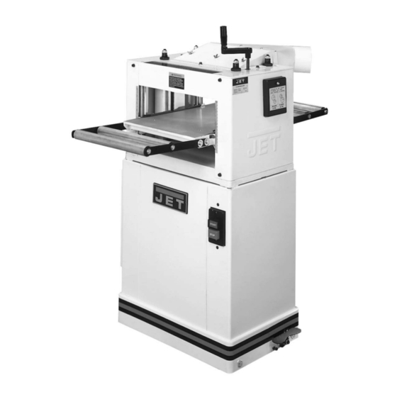
- Page 1 This .pdf document is bookmarked Operating Instructions and Parts Manual Planer/Molder Model JPM-13CS 427 New Sanford Road LaVergne, Tennessee 37086 Part No. M-708524 Ph.: 800-274-6848 Revision G3 10/2018 www.jettools.com Copyright © 2014 JET...
-
Page 2: Warranty And Service
JET sells through distributors only. The specifications listed in JET printed materials and on official JET website are given as general information and are not binding. JET reserves the right to effect at any time, without prior notice, those alterations to parts, fittings, and accessory equipment which they may deem necessary for any reason ®... -
Page 3: Table Of Contents
13.2 Back Relief Molding ..........................18 13.3 Tongue and Groove Molding ........................18 14.0 Maintenance ............................... 18 14.1 Lubrication .............................. 18 15.0 Troubleshooting the JPM-13CS ......................... 19 15.1 Mechanical and electrical problems ....................... 19 15.2 Performance problems ........................... 20 16.0 Replacement Parts ............................. 21 16.1.1 Table and Base Assembly –... -
Page 4: Safety Warnings
3.0 Safety warnings For your own safety, read this instruction manual before operating the tool. Wear Eye Protection KEEP GUARDS IN PLACE and in working order. REMOVE ADJUSTING KEYS AND WRENCHES. Form the habit of checking to see that keys and adjusting wrenches are removed from the tool before turning it on. -
Page 5: About This Manual
If there are questions or comments, please contact your local supplier or JET. JET can also be reached at our web site: www.jettools.com. -
Page 6: Electrical Connections
The 115V attachment plug, supplied with the planer/molder, must be replaced with a UL/CSA listed plug suitable for 230V operation, similar to the one shown in Figure 3. Contact your local Authorized JET Service Center or qualified electrician for proper procedures to install the plug. The planer/molder must... -
Page 7: On-Off Switch Padlock
The planer/molder with a 230 volt plug should only be connected to an outlet having the same configuration as illustrated by the grounded outlet box in Figure 3. No adapter is available or should be used with the 230 volt plug. Important: In all cases (115 or 230 volts), make certain the receptacle in question is properly grounded. -
Page 8: Specifications
∗ The use of a dust chute and adequate dust collection system is required for all molding operations. For a complete line of woodworking dust collectors, contact your local JET distributor, or visit our website at www.jettools.com. -
Page 9: Glossary
8.0 Glossary • Cutterhead (A, Figure 5) – metal cylinder that holds the planer knives or the molding cutters. • Table – part of machine over which the lumber passes. • Feed Rollers – two rubber covered cylinders that push lumber through the machine. •... -
Page 10: Setup And Assembly
Attach the top side of dust chute with three 9.0 Setup and assembly M5x10 machine screws, three washers. 9.1 Shipping contents Attach lower section of dust chute with three M6x8 machine screws, and three M6 washers. Molder/Planer Mount extension roller assembly to the middle Dust Chute table with four M8x12 hex cap bolts, and four Extension Roller Assemblies... -
Page 11: Feed Rate Adjustment
10.5 Knife adjustment Measure the cut piece. Adjust pointer accordingly. adjustment replacement of knives must be done to all three 10.3 Feed rate adjustment knives at the same time. Failure to comply may The planer/molder has two speeds that feed the result in an out-of-balance cutterhead which work piece, at 10 feet per minute (FPM) for will lead to bearing failure. -
Page 12: Knife Replacement
10.7 Adjusting infeed roller and 12. Repeat steps five through eleven for blades two and three. outfeed rollers for planing As a general rule of thumb, the infeed and outfeed 10.6 Knife replacement rollers are set 1/8” below the cutterhead (not the knives) at the factory. -
Page 13: Adjusting Chip Deflectors For Planing
The JPM-13CS is supplied with planing blades mounted in the cutterhead. Planing can be done at 10 FPM for an improved surface finish or 20 FPM Figure 12 for faster planing. -
Page 14: Wood Grain
Wood warped lengthwise - Feed rollers will Remove dust hood (B, Figure 14) and dust flatten a lengthwise warped board as if it were flat, chute. but the board will spring back to its original shape Loosen three wing nuts (C, Figure 14) and once out of the planer. -
Page 15: Setting Feed Rollers For Molding
• When using cutters larger than 2” wide, the feed Install special lock bar that is included with the rollers will have to be set 5/16” below the cutter knife set. Make sure set screws are loose to head. To set the feed rollers for molding: allow locking adjustment. -
Page 16: Making & Installing A Bedboard
12.3 Making & installing a bedboard You must use a board over the planer/molder table when molding. This prevents the knives from hitting the table and allows the knives to cut into the guide boards to clean up the sides of the molding. Disconnect machine from... -
Page 17: Molding Procedure
Position second guide rail on the table. Placement of this rail depends on the width of the board and if the board requires outer edge clean-up. Review molding procedure section for pre-sizing stock guidelines. When using knives that require outer edge clean-up, the workpiece will contact the guide rails only while wood is feeding into the cutterhead. -
Page 18: Back Relief Molding
12. Run all stock to be molded through the machine at this time. Note: If you are molding several boards with the same profile and have to make several passes to complete the profile, you must run all boards through at each setting. This assures all stock will match the desired shape. -
Page 19: Troubleshooting The Jpm-13Cs
15.0 Troubleshooting the JPM-13CS 15.1 Mechanical and electrical problems Trouble Probable Cause Remedy Table difficult to Lubricate corner posts and screws. Lack of lubrication on corner posts and adjust. screws. Chain is jumping. Inadequate tension. Adjust chain tension. Sprockets misaligned. -
Page 20: Performance Problems
15.2 Performance problems Trouble Probable Cause Remedy Snipe. Table rollers not set properly. Adjust rollers to proper height. Support long boards with extension Inadequate support of long boards. rollers. Uneven feed roller pressure front to Adjust feed roller pressure. back. Dull knives. -
Page 21: Replacement Parts
Number of your machine available when you call will allow us to serve you quickly and accurately. Non-proprietary parts, such as fasteners, can be found at local hardware stores, or may be ordered from JET. Some parts are shown for reference only, and may not be available individually. -
Page 22: Table And Base Assembly – Exploded View
16.1.1 Table and Base Assembly – Exploded View... -
Page 23: Table And Base Assembly – Parts List
16.1.2 Table and Base Assembly – Parts List Index No Part No Description Size 1 ....MHA-B01W ....Cover (left) ..................... 1 2 ....TS-0680021 ....Flat Washer ............. 1/4 ......... 8 3 ....TS-1503011 ....Hex Socket Cap Screw ..........M6x8 ......8 4 .... -
Page 24: Cutterhead And Roller Assembly - Parts List
16.2.1 Cutterhead and Roller Assembly – Parts List 16.2.2 Cutterhead and Roller Assembly – Parts List Index No Part No Description Size ....MHA-CW ....Dust Hood Assembly CP ................1 1 ....MHA-C01AW ..... Dust Hood ...................... 1 2 .... - Page 25 Index No Part No Description Size 15 ....PGE-B19C ....Stud ....................... 1 20 ....TS-1503021 ....Hex Socket Cap Screw .......... M6x10 ......1 21 ....MHA-C05 ....Spindle Pulley ....................1 22 ....TS-0680021 ....Flat Washer ............. 1/4 ......... 1 23 ....
-
Page 26: Gearbox Assembly - Parts List
16.3.1 Gearbox Assembly – Parts List... -
Page 27: Gearbox Assembly - Parts List
16.3.2 Gearbox Assembly – Parts List Index No Part No Description Size ....MHA-G ...... Gearbox Assy (#’s 1-33,35) (serial #810xxxx and lower) ....... 1 ....MHA-GUW ....Gearbox #’s (#’s 1-12,14,16-32,35-36) (serial #811xxxx and higher) .... 1 1 ....MHA-G01 ....Gearbox Body (serial #810xxxx and lower) ........... 1 .... -
Page 28: Stand And Motor Assembly - Parts List
16.4.1 Stand and Motor Assembly – Parts List... -
Page 29: Stand And Motor Assembly - Parts List
43 ....TS-2342101 ....Lock Nut..............M10x1.5 ......1 44 ....TS-1550041 ....Flat Washer ............. M6 ......... 4 45 ....HS020440 ....Hex Socket Cap Screw ..........M6x70 ......4 ....STRIPE-1-3/4 .... JET Stripe (not shown) ..........1-3/4”W ....per ft. -
Page 30: Electrical Connections
17.0 Electrical Connections... - Page 32 427 New Sanford Road LaVergne, Tennessee 37086 Phone: 800-274-6848 www.jettools.com...
Need help?
Do you have a question about the JPM-13CS and is the answer not in the manual?
Questions and answers