Table of Contents
Advertisement
Quick Links
ISL85003DEMO1Z, ISL85003ADEMO1Z Evaluation
Board User Guide
Description
The ISL85003 and ISL85003A Demo kits are intended for use
for point-of-load applications sourcing from 4.5V to 18V. The
kits are used to demonstrate the performance of the
ISL85003 and ISL85003A, high efficiency synchronous buck
regulators. The ISL85003 and ISL85003A are offered in a
4x3mm dual flat no lead (DFN) package.
Recommended Equipment
The following materials are recommended to perform testing:
• 0V to 25V power supply with at least 10A source current
capability
• Electronic loads capable of sinking current up to 7A
• Digital Multimeters (DMMs)
• 100MHz quad-trace oscilloscope
Key Features
• Input voltage range 4.5V to 18V
• Current mode control
- DCM/PWM
- Internal or external compensation options
- 500kHz switching frequency option
- External synchronization up to 2MHz on ISL85003
• Adjustable soft-start time on the ISL85003A
• Continuous output current up to 3A
• Minimal external components required
References
ISL85003, ISL85003A
Datasheet
Ordering Information
PART NUMBER
ISL85003DEMO1Z
Small form factor Demo board for 3A,
4.5V to 18V Switching Regulator, external
synchronization.
ISL85003ADEMO1Z
Small form factor Demo board for 3A,
4.5V to 18V Switching Regulator,
adjustable soft-start time
May 16, 2014
AN1935.0
DESCRIPTION
1
CAUTION: These devices are sensitive to electrostatic discharge; follow proper IC Handling Procedures.
1-888-INTERSIL or 1-888-468-3774
Quick Setup Guide
1. Ensure that the circuit is correctly connected to the supply
and loads prior to applying any power.
2. Connect the bias supply to VIN, the plus terminal to VIN and
the negative return to PGND.
3. Turn on the power supply.
4. Verify the output voltage is 5V for V
Evaluating the Other Output Voltage
The ISL85003DEMO1Z kit output is preset to 5V; however,
output voltages are programmed using an external resistor
divider that scales the feedback relative to the internal
reference voltage. Please refer to the application note
and the
ISL85003, ISL85003A
Disabling/Enabling Function
The ISL85003DEMO1Z board has EN pin tied to VIN via R
This keeps the part enabled all the time. To disable the part,
remove R
.
7
MODE/SS Control
The ISL85OO3 evaluation board has a MODE pin that allows
different mode operation. Default board configuration has
R
= 200k to V
, which defaults to PWM operation mode. If
6
CC
this pin is tied to GND the IC will operate in CCM mode.
The ISL85OO3A evaluation board has an SS pin that provides a
programmable soft-start. When the chip is enabled, the
regulated 4μA pull-up current source charges a capacitor C
connected from SS to ground. Default board configuration has
R
= 200k to V
, which defaults to internal SS.
6
CC
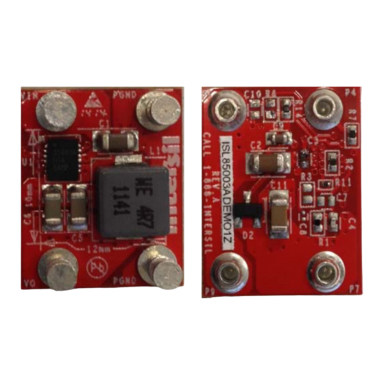
TOP SIDE
FIGURE 1. ISL85003ADEMO1Z PICTURES
Copyright Intersil Americas LLC 2014. All Rights Reserved.
|
Intersil (and design) is a trademark owned by Intersil Corporation or one of its subsidiaries.
All other trademarks mentioned are the property of their respective owners.
Application Note 1935
OUT.
datasheet for further information.
BOTTOM SIDE
AN1930
.
7
10
Advertisement
Table of Contents

Related Manuals for Intersil ISL85003DEMO1Z


Summary of Contents for Intersil ISL85003DEMO1Z
-
Page 1: Application Note
CAUTION: These devices are sensitive to electrostatic discharge; follow proper IC Handling Procedures. Copyright Intersil Americas LLC 2014. All Rights Reserved. AN1935.0 1-888-INTERSIL or 1-888-468-3774 Intersil (and design) is a trademark owned by Intersil Corporation or one of its subsidiaries. All other trademarks mentioned are the property of their respective owners. - Page 2 Application Note 1935 ISL85003ADEMO1Z Board Layout FIGURE 3. SILK SCREEN BOTTOM FIGURE 2. SILK SCREEN TOP ISL85003ADEMO1Z Schematic BOOT BOOT EN/SS UNNAMED_1_SMCAP_I186_A 10UF 10UF COMP PHASE 301K AGND PHASE UNNAMED_1_SMCAP_I185_A UNNAMED_1_SMCAP_I193_A 0.1UF 4.7PF ISL85003AFRZ UNNAMED_1_POWERIND_I179_A 4.7UH 57.6K 22UF 22UF 22UF NOTE: If the IC is used in an application where the input test leads have large parasitic inductance, the input electrolytic capacitor C may be added to prevent transient...
- Page 3 ERJ-2RKF5762X TF, ROHS Intersil Corporation reserves the right to make changes in circuit design, software and/or specifications at any time without notice. Accordingly, the reader is cautioned to verify that the Application Note or Technical Brief is current before proceeding.
Need help?
Do you have a question about the ISL85003DEMO1Z and is the answer not in the manual?
Questions and answers