Table of Contents
Advertisement
Quick Links
Isl85014Eval1Z Evaluation Board User Guide
Description
The
ISL85014
is a 3.8V to 18V input, 14A synchronous buck
regulator for applications with input voltage from multi-cell
batteries or regulated 5V and 12V power rails. The device also
provides an integrated bootstrap diode for the high-side gate
driver to reduce the external parts count. The ISL85014EVAL1Z
platform allows quick evaluation of the high-performance
features of the ISL85014 buck regulator.
Specifications
This board has been configured and optimized for the following
operating conditions:
• Input voltage ranges from 4.5V to 18V
• 1.8V nominal output voltage
• Up to 14A output current capability
• Default internally set to 600kHz switching frequency
• Default internally set to 3ms soft-start
• Operating temperature range: -40°C to +85°C
PVIN
4.5V TO 18V
GND
February 15, 2017
UG113.0
15
14
13
VIN
EN
DNC
PVIN
C
PHASE
IN
GND
SYNC
MODE
FREQ
1
2
3
FIGURE 1. BLOCK DIAGRAM
1
CAUTION: These devices are sensitive to electrostatic discharge; follow proper IC Handling Procedures.
Key Features
• Switch selectable EN (enabled/disabled)
• Frequency synchronization option
• Jumper selectable mode (DEM/Forced CCM)
• Jumper selectable OCP mode (Hiccup/Latch-off)
• Jumper selectable frequency (600kHz/300kHz)
• Connectors and test points for easy probing
• Compact design
Related Literature
• For a full list of related documents, visit our website
-
ISL85014
product pages
Ordering Information
PART NUMBER
ISL85014EVAL1Z
R
R
2
3
12
11
10
DNC
COMP
FB
9
8
C
7
PG
VDD
BOOT
4
5
6
C
3
|
1-888-INTERSIL or 1-888-468-3774
Intersil (and design) is a trademark owned by Intersil Corporation or one of its subsidiaries.
All other trademarks mentioned are the property of their respective owners.
User Guide 113
DESCRIPTION
Evaluation board for ISL85014FRZ
R
1
C
1
L1
V
OUT
1.8V/14A
C
OUT
4
GND
Copyright Intersil Americas LLC 2017. All Rights Reserved
Advertisement
Table of Contents

Related Manuals for Intersil ISL85014EVAL1Z


Summary of Contents for Intersil ISL85014EVAL1Z
-
Page 1: Key Features
CAUTION: These devices are sensitive to electrostatic discharge; follow proper IC Handling Procedures. 1-888-INTERSIL or 1-888-468-3774 Copyright Intersil Americas LLC 2017. All Rights Reserved UG113.0 Intersil (and design) is a trademark owned by Intersil Corporation or one of its subsidiaries. All other trademarks mentioned are the property of their respective owners. - Page 2 The ISL85014 can be synchronized to an external clock with Power-good output frequency ranges from 100kHz to 1MHz by applying the external clock to test point SYNC on the ISL85014EVAL1Z evaluation Selection Switch and Jumper board. The external clock should meet the specifications of pulse...
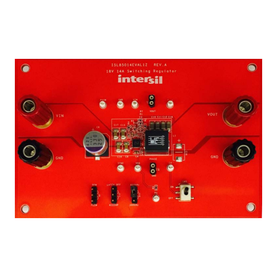
- Page 3 6. Connect the GND of the IC to the ground planes underneath capacitors with lower ESL for the input capacitors, and place using multiple thermal vias to improve thermal performance. them as close to the IC as possible. ISL85014EVAL1Z Evaluation Board FIGURE 2. TOP VIEW Submit Document Feedback UG113.0...
- Page 4 User Guide 113 ISL85014EVAL1Z Schematic Disable SW SPDT Enable 100k 200k 100k PVIN PVIN ISL85014 VOUT PHASE 0.68uH 22uF 330uF/25V 22uF 22uF 100uF 100uF 100uF 100n SYNC 100k 2.2uF FIGURE 3. ISL85014EVAL1Z SCHEMATIC Submit Document Feedback UG113.0 February 15, 2017...
-
Page 5: Bill Of Materials
JOHNSONS Jumper CONN-JUMPER, SHORTING, 2PIN, BLK, OPEN TOP, 2.54mmPITCH, ROHS 929950-00 R3, R5 RES, SMD, 0402, DNP, TF, ROHS C1, C2, C3, C16 CAP, SMD DNP-PLACE HOLDER, ROHS PWB-PCB, ISL85014EVAL1Z, REVA, ROHS ISL85014EVAL1Z Submit Document Feedback UG113.0 February 15, 2017... - Page 6 User Guide 113 ISL85014EVAL1Z PCB Layout FIGURE 4. TOP LAYER FIGURE 5. LAYER 2 FIGURE 7. BOTTOM LAYER FIGURE 6. LAYER 3 Submit Document Feedback UG113.0 February 15, 2017...
- Page 7 FIGURE 11. OUTPUT VOLTAGE RIPPLE, I = 14A Intersil Corporation reserves the right to make changes in circuit design, software and/or specifications at any time without notice. Accordingly, the reader is cautioned to verify that the document is current before proceeding.
Need help?
Do you have a question about the ISL85014EVAL1Z and is the answer not in the manual?
Questions and answers