
Related Manuals for Intersil ISL8215MEVAL1Z


Summary of Contents for Intersil ISL8215MEVAL1Z
- Page 1 ISL8215MEVAL1Z User’s Manual: Evaluation Board Industrial Analog and Power Rev 0.00 Aug 2017...
-
Page 2: Key Features
The ISL8215MEVAL1Z evaluation board is a 1.8inx3in 4-layer FR4 board with 2oz. copper on all layers. Operating from a single 7V to 42V wide input power rail, the ISL8215MEVAL1Z evaluation board offers adjustable output voltages down to 0.6V and efficiencies of up to 96.5%. -
Page 3: Related Literature
SGND PGND 10µF 47nF 1µF Figure 1. ISL8215MEVAL1Z Block Diagram Recommended Testing Equipment • 0V to 42V power supply with at least 12A source current capability • Electronic loads capable of sinking current up to 15A • Digital Multimeters (DMMs) •... -
Page 4: Functional Description
2. Functional Description Functional Description The ISL8215MEVAL1Z provides the peripheral circuitry to evaluate the feature set of the ISL8215M. The evaluation board is designed with mechanical switches for ENABLE, several connectors, test points, and jumpers, which makes validation of the module easy. The converter can be enabled and disabled by toggling the ENABLE switch as shown in Figure 2 on page 6. -
Page 5: Pcb Layout Guidelines
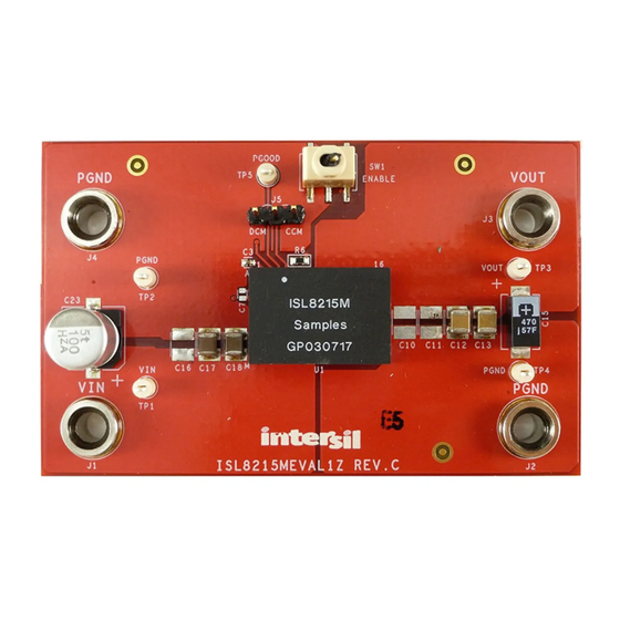
ISL8215MEVAL1Z 3. PCB Layout Guidelines PCB Layout Guidelines The ISL8215MEVAL1Z evaluation board is a 1.8inx3in four-layer FR-4 board with 2oz. copper on all the layers. The board can be used as a single 15A reference design. Refer to Figures 15 through for board layout information. - Page 6 ISL8215MEVAL1Z 3. PCB Layout Guidelines PGOOD TEST POINT ENABLE SWITCH CCM/DEM SELECTION Figure 2. Top of Board SW FREQUENCY PROGRAMMING RESISTOR PROGRAMMING RESISTOR Figure 3. Bottom of Board UG105 Rev.0.00 Page 6 of 14 Aug 14, 2017...
- Page 7 ISL8215MEVAL1Z Schematic 575-4 40.2K 575-4 PGND MOD/SYNC PAD5 MOD/SYNC PHASE 575-4 PGOOD PAD2 VOUT PGOOD VOUT 100K VOUT1 ISL8215MIRZ SS/TRK SS/TRK 575-4 PAD1 PAD3 PGND SGND PGND Figure 4. Schematic...
- Page 8 ISL8215MEVAL1Z 3. PCB Layout Guidelines Typical Evaluation Board Performance Curves The following data was acquired using the ISL8215MEVAL1Z evaluation board at +25°C ambient and free air 0LFM. 0.9Vout, 300kHz 1Vout, 300kHz 0.9Vout, 300kHz 1Vout, 300kHz 1.2Vout, 300kHz 1.5Vout, 300kHz 1.2Vout, 300kHz 1.5Vout, 300kHz...
- Page 9 ISL8215MEVAL1Z 3. PCB Layout Guidelines Typical Evaluation Board Performance Data Operating condition: V = 24V, f = 300kHz, CCM Mode, unless otherwise noted. EN 1V/DIV 100mV/DIV 1V/DIV PGOOD 2V/DIV 5A/DIV 500µs/DIV 5ms/DIV Figure 11. Transient Response, V = 3.3V, 0A to 7.5A, Figure 12.
-
Page 10: Bill Of Materials
ISL8215MEVAL1Z 3. PCB Layout Guidelines Bill of Materials Reference Package Designators Qty Value Tol. Voltage Power Type Manufacturer Part Number Description 470µF ±20% 6.3V 2917 Panasonic 6TPF470MAH POSCAP C12, C13, 100µF ±20% 1210 Murata LMK325BJ107MM-T Ceramic C27, C28 Capacitor C10, C11, OPEN ±20%... - Page 11 ISL8215MEVAL1Z 3. PCB Layout Guidelines Reference Package Designators Qty Value Tol. Voltage Power Type Manufacturer Part Number Description ±1% 1/10W 0603 Metal Film Chip Resistor 475kΩ ±1% 1/16W 0402 Yageo RC0402FR-07475KL Chip Resistor 20Ω ±1% 1/10W 0603 Panasonic ERJ-3EKF20R0V Chip Resistor 0Ω...
- Page 12 ISL8215MEVAL1Z 3. PCB Layout Guidelines ISL8215MEVAL1Z PCB Layout Figure 16. Top Layer Component Side Figure 15. Silkscreen Top Figure 17. Inner Layer 2 Figure 18. Inner Layer 3 Figure 19. Bottom Layer Solder Side Figure 20. Silkscreen Bottom UG105 Rev.0.00...
-
Page 13: Revision History
All trademarks and registered trademarks are the property of their respective owners. Intersil Corporation reserves the right to make changes in circuit design, software and/or specifications at any time without notice. Accordingly, the reader is cautioned to verify that the document is current before proceeding. - Page 14 ISL8215MEVAL1Z UG105...
Need help?
Do you have a question about the ISL8215MEVAL1Z and is the answer not in the manual?
Questions and answers