
Related Manuals for Entrematic EM EMSW


Summary of Contents for Entrematic EM EMSW
- Page 1 Swing Door Operator EM EMSW 1 2 3 4 5 6 7 8 Installation and Service Manual Original instructions 1004291-EMEI-10.0 Issue 2016-01-27...
- Page 2 © All rights in and to this material are the sole property of Entrematic Group AB. Copying, scanning, alterations or modifications are expressly forbidden without the prior written consent of Entrematic Group AB. Rights reserved for changes without prior notice.
-
Page 3: Table Of Contents
5.4.8 LockOut ................................... 5.4.9 Programme selector ..............................Models ......................................EM EMSW, standard cover (wall or door leaf mounted) ....................Part identification & Accessories ............................Arm systems, PUSH ..................................Arm systems, PUSH-335 ................................Arm system, PULL ................................... Arm system, PULL-220 ................................. - Page 4 Steel frame with glass ..............................15.3.3 Solid wood ..................................Installation instructions for Accessories ......................... 16.1 COOA - Coordination unit ................................16.1.1 EM EMSW 2 - Push ................................ 16.1.2 EM EMSW 2 - Pull ................................16.2 PAG ........................................16.3 Door stop ......................................
-
Page 5: Revision
1 Revision Revision Following pages have been revised: Page Revision 9.0 → 10.0 Updated illustration with arm. Added this new section. Updated Art. No., texts and illustration with arm. Added PUSH-335. Updated Art. No., texts and illustration with arm. Updated Art. No. and deleted 600149. Updated texts. -
Page 6: Instructions For Safe Operation
2 Instructions for safe operation Instructions for safe operation • Failure to observe the information in this manual may result in personal injury or damage to equipment. • To reduce the risk of injury to persons - use this operator with single or double pedestrian swinging or folding doors only. -
Page 7: Important Information
This manual contains the necessary details and instructions for the installation, maintenance and service of the Swing Door Operator EM EMSW. The EM EMSW is an automatic swing door operator developed to facilitate entrances to buildings and within buildings through swing doors. The EM EMSW is an electrohydraulic operator approved for fire door applications. -
Page 8: Electronic Equipment Reception Interference
Environmental requirements Entrematic Group products are equipped with electronics and may also be equipped with batteries containing materials which are hazardous to the environment. Disconnect power before removing electronics and battery and make sure it is disposed of properly according to local regulations (how and where) as was done with the packaging material. -
Page 9: Technical Specification
For PULL = 28 kg m Inertia = Door weight x (Door width) The EM EMSW complies with the door weights/widths stated in the: Controlled door closing, EN 1154 Table I, size 3-6 Coordination unit for rebated doors, EN 1158 Türschliesser mit Öffnungsautomatik (Drechflügelantrieb), DIN 18263-4 AU Grösse... - Page 10 4 Technical specification This product is to be installed internally. Classification to DIN 18650-1 Digit 1 Digit 2 Digit 3 Digit 4 Digit 5 Digit 6 Digit 7 Digit 8 1,2,3 1,2,3,4 1,2,3,4 Type of drive, digit 1. swing door drive Drive durability, digit 2.
-
Page 11: Permitted Door Weight And Door Width
4 Technical specification Permitted door weight and door width PUSH arm J=80 kgm² PUSH arm PULL arm PULL arm J=28 kgm² Door width (m) 1004291-EMEI-10.0 Issue 2016-01-27... -
Page 12: How The Em Emsw Works
How the EM EMSW works The EM EMSW works electro-hydraulically. It opens with an AC-motor that via a hydraulic unit and an arm system transmits the power to the door leaf. The closing power is from a coil spring. The movement of the door is controlled by limit switches and valve screws. -
Page 13: Multi Voltage Input (Mvi)
5 How the EM EMSW works 5.3.3 Multi Voltage Input (MVI) MVI impulse accepts a potential-free contact or 6-24 V AC/DC. Status of lock (operation mode) can be selected via a function selector FS2 and depends on input TB2:11 and 13. -
Page 14: Kill Input
5 How the EM EMSW works 5.3.4 Kill Input When kill is activated, the door will close immediately if not already closed. Hold open and low pass filter timers are reset. Key impulse will open lock during activated kill if not connected to TB2:5 for 0 V DC. -
Page 15: Double Door
5 How the EM EMSW works 5.3.8 Double Door The CSDB works as the master in a double door application and is connected to the slave unit CSDA-S. The slave unit has a standard opening delay of 0,2 sec. The delay can be increased to 0,5 sec. to prevent jamming of thicker door leaves. -
Page 16: Presence Impulse
5 How the EM EMSW works 5.4.3 Presence Impulse Presence impulse will prevent an open door from closing and will re-open a closing door and the control will make sure that the hold open time is not shorter than 1,5 s. -
Page 17: Programme Selector
5 How the EM EMSW works 5.4.9 Programme selector Programme selector PS-4C can be connected to the EXB. The PS-4C, compared to PS-3B, has a fourth position EXIT that will make the CSDB ignore the outer impulse device. Presence sensors are enabled in all programme selector settings but not when kill is active. -
Page 18: Models
The operator are non-handed and not dependent on the hinges. The operator suits both pushing and pulling arm systems. EM EMSW, standard cover (wall or door leaf mounted) EM EMSW is the standard operator. Pushing arm system on a wall-mounted and on a door leaf- mounted operator shown. Wall mounted... -
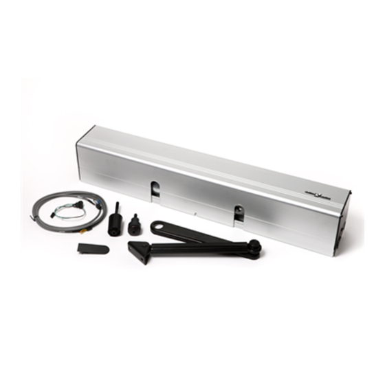
Page 19: Part Identification & Accessories
7 Part identification & Accessories Part identification & Accessories 1 2 3 4 5 6 7 8 Description Description Mounting plate Extension unit, EXB (option) Motor/pump End plate Magnetic valve Programme selector, PS-3B (option) Hydraulic unit Cover Drive shaft Bearing sleeve Spring tube Cable holder Cable inlet... -
Page 20: Arm System, Pull
7 Part identification & Accessories Arm system, PULL Art. No. 1011707BK/SI PULL It is used if the operator is installed on the wall on the same side as the door swing. Arm system, PULL-220 Art. No. 1014114BK/SI PULL-220 It is used if the operator is installed on the wall on the same side as the door swing and when the door is 450-700 mm wide. -
Page 21: Further Accessories
7 Part identification & Accessories Further accessories 4-Position Switch 2-Position Switch 3-Position Extension unit (with EXB) Switch PS-3B PSW-2 PSK-2 PS-4C Art. No. 1004116 ILL-01578 Art. No. Art. No. 1004117 655845 Art. No. Art. No. 655843 655844 Coordination unit, COOA PULL-Arm Reveal Spacer Middle piece kit Art. - Page 22 7 Part identification & Accessories Drive Shaft Extension Kits Control unit, CSDA-F Art. No. 600081 70 mm (2-3/4") 50 mm (2") 20 mm (3/4") Drilling template Art. No. 1000219 Art. No. Art. No. Art. No. 173107/173107SI 173108/173108SI 173109/173109SI Tool kit to change rotation direction Restore after alarm button Limit Switch Art.
-
Page 23: Labels
7 Part identification & Accessories Labels Label kit - including all below Art. No. 1005227 Emergency break-out, DIN right door Art. No. 1001785 Emergency break-out, DIN left door Art. No. 1001786 Activation by disabled people Click! Art. No. 1003963 Operator designed for disabled people Art. -
Page 24: Pre-Installation
Expansion shell bolt, min. M6x85, UPAT PSEA B10/25, min. 50 mm from the underside * Entrematic Group minimum recommended requirements. Building Codes may give different specifications. Refer to AHJ (Authority Having Jurisdiction). ** Thinner wall profiles must be reinforced with rivnuts. -
Page 25: Tools Required
8 Pre-Installation Tools required • Torx T8, T10, T20 and T25 • Metric hexagonal key 3, 4 and 6 mm • Flatblade screwdriver, small • Torque wrench with metric Allen socket 6 mm Installation on double doors If the operators are to be mounted at the same height with pushing and pulling arm systems, the height is determined by the pulling arm system, PULL/ST. -
Page 26: Installation Examples For Fire Approved Doors
8 Pre-Installation Installation examples for fire approved doors Illustrations below show examples of approved reinforcements when mounting a fireproof swing door operator. Note! The type approval for fireproof swing doors is valid only with the arm system PUSH. Reveal max 480 mm and shaft extension max 70 mm. Description Description Steel min. -
Page 27: Mechanical Installation
9 Mechanical installation Mechanical installation This instruction comprises the installation of the EM EMSW with arm systems PUSH, which push the door open and PULL / ST-V/H, which pull the door open. See also “QuickStart” which is enclosed with each operator. - Page 28 9 Mechanical installation Cont. Wall mounted operator with arm system PUSH” ø 16 mm (Cable inlet hole) Issue 2016-01-27 1004291-EMEI-10.0...
- Page 29 9 Mechanical installation Cont. Wall mounted operator with arm system PUSH” Adjust +/– 1 tooth = ± 5° 90° 25 Nm 90° 1004291-EMEI-10.0 Issue 2016-01-27...
-
Page 30: Door Leaf Mounted Operator With Arm System Push-335
9 Mechanical installation Door leaf mounted operator with arm system PUSH-335 108,5 108,5 max. 135 min. 50 min. 45 min. 45 min. 120 min. 120 Pivot or butt hinges Operator drive shaft Cable inlet at end plate Door mounting kit, Art. No. 100132, optional Reinforcements required in door leaf and at the fixing holes... -
Page 31: Wall Mounted Operator With Arm System Pull, Pull-220 And St
9 Mechanical installation Wall mounted operator with arm system PULL, PULL-220 and ST Note! If the operator is not ordered for pulling arm system, the direction of rotation must be re- versed. 9.3.1 Changing the direction of rotation 165˚ ILL-01556 1004291-EMEI-10.0 Issue 2016-01-27... -
Page 32: Installation Of Operator With Arm System Pull
9 Mechanical installation 9.3.2 Installation of operator with arm system PULL Top of door ≤ 60 40 x 60 (turnable) Drilling template Art. No. 1000219 ø 5,1 mm, 8x Issue 2016-01-27 1004291-EMEI-10.0... - Page 33 9 Mechanical installation Cont. Installation of operator with arm system PULL” ø 16 mm (Cable inlet hole) Connect mains power 1004291-EMEI-10.0 Issue 2016-01-27...
- Page 34 9 Mechanical installation Cont. Installation of operator with arm system PULL” 25 Nm Issue 2016-01-27 1004291-EMEI-10.0...
- Page 35 9 Mechanical installation Cont. Installation of operator with arm system PULL” Click Click 1004291-EMEI-10.0 Issue 2016-01-27...
-
Page 36: Installation Of Operator With Arm System St
9 Mechanical installation 9.3.3 Installation of operator with arm system ST A = 0 - 60 A > 60 - 100 (Optional) Top of door Outside open door Drilling template Art. No. 1000219 ø 5,1 mm, 6x Issue 2016-01-27 1004291-EMEI-10.0... - Page 37 9 Mechanical installation Cont. Installation of operator with arm system ST” Outside open door ø 16 mm (Cable inlet hole) Outside open door 1004291-EMEI-10.0 Issue 2016-01-27...
- Page 38 9 Mechanical installation Cont. Installation of operator with arm system ST” Connect mains power Note, the way of mounting the arm! Issue 2016-01-27 1004291-EMEI-10.0...
- Page 39 9 Mechanical installation Cont. Installation of operator with arm system ST” 25 Nm 0º ≈ 90º ≈ 45º 1004291-EMEI-10.0 Issue 2016-01-27...
- Page 40 9 Mechanical installation Cont. Installation of operator with arm system ST” Break-out Issue 2016-01-27 1004291-EMEI-10.0...
- Page 41 9 Mechanical installation Cont. Installation of operator with arm system ST” ø 5,1 mm, 2x 1004291-EMEI-10.0 Issue 2016-01-27...
-
Page 42: Electrical Connection
10 Electrical connection Electrical connection Note! During any work with the electrical connections the mains power must be disconnected. • Place the electric switch easily accessible from the operator. If a plug contact is used in the in- stallation the wall socket shall be placed easily accessible from the operator. •... -
Page 43: Connection Of Control Unit Csdb Single Doors
10 Electrical connection 10.2 Connection of control unit CSDB single doors Connect the mains power to the mains terminal block. Note! Accessories and activation units must not be connected until the adjustment of speeds etc. has been carried out. Note! It is important that the high and low voltage cables are well separated and fixed. The high voltage cables must be routed and fixed on one side of the drive unit by using the enclosed cable holders and the low voltage cables must be routed on the opposite side using the same type of cable holders. -
Page 44: Connection Of Control Units Csdb And Csda-S Double Doors
10 Electrical connection 10.3 Connection of control units CSDB and CSDA-S double doors For double door operators, both operators have to be connected to the mains. A six-pole cable (enclosed) has to be connected between TB1 on the CSDB and TB6 on the CSDA-S. Note! It is important that the high and low voltage cables are well separated and fixed. -
Page 45: Connection Of Control Units Csdb/Csdb Double Doors
10 Electrical connection 10.4 Connection of control units CSDB/CSDB double doors For double door operators both operators have to be connected to the mains. A three-pole cable (not enclosed) has to be connected between TB1 on the CSDB (master) and TB2 on the CSDB (slave). -
Page 46: Connection Of Extension Unit Exb Option
10 Electrical connection 10.5 Connection of extension unit EXB option The extension unit EXB is to be installed on top of the CSDB. a Connect the flat cable on the EXB to the CSDB. b Snap on the EXB to the CSDB. Blanking switch Presence impulse configuration Blanking switch... -
Page 47: Sensor Cable Inlet
10 Electrical connection 10.6 Sensor cable inlet Alt. 1 Alt. 1 Alt. 1 Alt. 2 Alt. 2 Alt. 2 ø 3,7 1004291-EMEI-10.0 Issue 2016-01-27... -
Page 48: Start-Up
11 Start-Up Start-Up Adjust the operator to have maximum 25% duty cycle, which means motor run time. Give a short opening impulse by strapping the impulse input and adjust if necessary as follows. See also illustration under Closing torque. See the “Guide for installers of Powered Pedestrian Swing Doors”, document PRA-0006, for calcu- lation of speed. -
Page 49: Opening Torque
11 Start-Up 11.2 Opening torque If the closing torque (spring force) has been changed, or if the door does not open to its full extent, the opening torque (pump pressure) must be adjusted as follows: a The factory set torque for PUSH is 70 Nm and for PULL 40 Nm at a door opening angle of 0-2°. b Measure the opening torque by using a spring balance and adjust if necessary. -
Page 50: Connection Of Activation Units And Accessories
11 Start-Up 11.3 Connection of activation units and accessories See sensor manuals for mounting and adjustments. Protective device shall comply with EN 12978. (SuperScan) AK / ES-P 4 SAFE Bodyguard EYE-TECH (monitored) PB… SR120-1 1 2 3 4 5 6 7 AK / ES-P 4 SAFE 1 2 3... -
Page 51: Cover
12 Cover Cover The cover and mounting plate are manufactured in clear anodized aluminium. The end plates are made of steel. 12.1 Fitting and removing the cover Break off and snap on the fill cover into the mounting plate for output shaft. Snap on the other fill cover for the second slot. -
Page 52: Middle Piece Cover
12 Cover 12.2 Middle piece cover X - 8 Cover Cover Issue 2016-01-27 1004291-EMEI-10.0... -
Page 53: Signage
Product label: Mandatory Emergency break-out: Mandatory, if approved for escape route. Entrematic Group door sticker: Mandatory, if applicable to highlight the presence of the glass (applied to all glass sections that are moving). Supervision of child: Mandatory, if applicable (applied to both sides of the door). To be placed on entrances where the risk analysis shows use by children, elderly and disabled. -
Page 54: Installation On Fire Doors
14 Installation on fire doors Installation on fire doors • The EM EMSW is approved in accordance with DIN 18263-4 for use on fire doors. The approval covers compliance with EN1154 Table 1, sizes 3-6, for use on fire doors with controlled door closing. -
Page 55: Connection Of Control Unit Csda-F Single Door
14 Installation on fire doors 14.1.1 Connection of control unit CSDA-F single door Note! It is important that the high and low voltage cables are well separated and fixed. The high voltage cables must be routed and fixed on one side of the drive unit by using the enclosed cable holders and the low voltage cables must be routed on the opposite side using the same type of cable holders. -
Page 56: Connection Of Control Unit Csda-F Double Door
14 Installation on fire doors 14.1.2 Connection of control unit CSDA-F double door Mains Mains CSDB CSDA-F CSDA-S 1 2 3 4 5 6 7 8 Mains Mains “Master” "Master" “Slave” "Slave" 1 2 3 4 5 6 7 8 Mains power 230V AC - 50 Hz, 10A 14.1.3... -
Page 57: Automation Of Fire Doors Without Overriding Fire Detection And Alarm System
14 Installation on fire doors 14.2 Automation of fire doors without overriding fire detection and alarm system 14.2.1 General connection For this type of installation the required fire detectors are direct-connected to the CSDA-F. CSDA - F Alarm +24 V Potential free contact alarm LED green Close door button... -
Page 58: Connection Of Csda-F To A Fire Alarm System
14 Installation on fire doors The capacity of the fire alarm system power supply is calculated according to the number of CSDA- F used x 0,05 A. 14.3.1 Connection of CSDA-F to a fire alarm system CSDA-F # 1 Fire alarm system (by others) Potential free contact with breaking capacity. -
Page 59: Installation And Adjustments - Low Energy Operator
15 Installation and adjustments - Low Energy Operator Installation and adjustments - Low Energy Operator To limit entrapment force and push opening force, parameters to work with are pump pressure, opening and closing time, spring tension and the way the PUSH arm system is mounted. The PULL arm system is standard mounted. -
Page 60: Swing Doors Opening And Closing Time
15 Installation and adjustments - Low Energy Operator 15.2 Swing Doors Opening and Closing Time Adjust, as a minimum, the operator's opening and closing time according to the diagram below. 15.2.1 How to find the correct opening and closing time •... -
Page 61: Aluminium Frame With Glass
15 Installation and adjustments - Low Energy Operator 15.3.1 Aluminium frame with glass Door leaf weight [kg] 8/24/8 glass 12 mm glass 6/10/6 glass 10 mm glass 8 mm glass 6 mm glass Door leaf area [m Example 15.3.2 Steel frame with glass Door leaf weight [kg] 10 mm glass 8 mm glass... -
Page 62: Solid Wood
15 Installation and adjustments - Low Energy Operator 15.3.3 Solid wood Door leaf weight [kg] 60 mm wood 50 mm wood 40 mm wood 30 mm wood 20 mm wood Door leaf area [m Issue 2016-01-27 1004291-EMEI-10.0... -
Page 63: Installation Instructions For Accessories
16 Installation instructions for Accessories Installation instructions for Accessories 16.1 COOA - Coordination unit 16.1.1 EM EMSW 2 - Push d o o v e " " S l a " d o s t e r " M a “Master”... -
Page 64: Em Emsw 2 - Pull
16 Installation instructions for Accessories 16.1.2 EM EMSW 2 - Pull " ) ( 1 0 9 7 8 0 a x . 2 " ) " ) , m ( 1 2 6 ( 4 6 2 0 0 a x . -
Page 65: Pag
16 Installation instructions for Accessories 16.2 Alternative PC-board fixing hole depending Remove screw before installing on mounting side and if "Push" or "Pull" PC-board fixing and CSDB adjustment screw 5 6 7 9 10 1112 Black Green Hall-switch A – A Magnet Adjustment of impulse sensitivity α... -
Page 66: Door Stop
16 Installation instructions for Accessories 16.3 Door stop • Install door stop to top side of output spindle to prevent door from extending beyond 90º. • Mount door stop when door is in open position with a clearance of 2 mm (2/32") as shown below. Fine adjust, if necessary, on limit switch and/or on armsystem. -
Page 67: Troubleshooting
17 Troubleshooting Troubleshooting Fault Possible reasons why Remedies/Explanation The door does not open Programme selector is set to OFF Change setting - The motor does not start Motor power is missing Check motor cable Mains power is missing Check power Fuse has blown Replace fuse Activation unit does not function... -
Page 68: Service/Maintenance
Service/Maintenance Regular inspections shall be made according to national regulations and product documentation by a Entrematic Group-trained and qualified technician. The number of service occasions should be in accordance with national requirements and product documentation. This is especially im- portant when the installation concerns a fire-approved door or a door with an emergency opening function. - Page 70 Entrematic Group AB, Lodjursgatan 10, SE-261 44 Landskrona, Sweden Tel: +46 10 47 48 300 • Fax: +46 418 201 15 www.entrematic.com • info.em@entrematic.com...
Need help?
Do you have a question about the EM EMSW and is the answer not in the manual?
Questions and answers