
Subscribe to Our Youtube Channel
Related Manuals for Clarke AC7000


Summary of Contents for Clarke AC7000
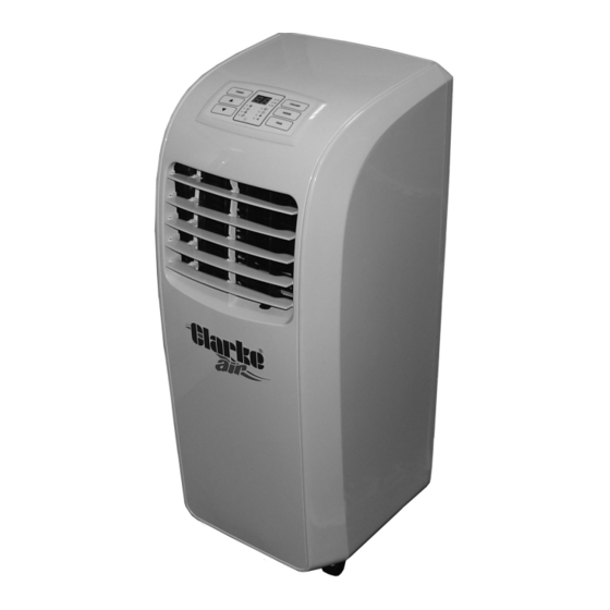
- Page 1 PORTABLE AIR CONDITIONER MODEL NO: AC7000 PART NO: 3230565 OPERATION & MAINTENANCE INSTRUCTIONS ORIGINAL INSTRUCTIONS GC0518 ISS 3...
-
Page 2: Environmental Protection
GUARANTEE This CLARKE product is guaranteed against faulty manufacture for a period of 12 months from the date of purchase. Please keep your receipt as proof of purchase. -
Page 3: Safety Warnings
3. This appliance is designed for use in residential environments and must not be used for other purposes. 4. If the appliance requires repair, always contact your CLARKE dealer. Always insist on original spare parts. Repairs carried out by unauthorized persons may be dangerous and invalidate the guarantee. -
Page 4: Electrical Connections
ELECTRICAL CONNECTIONS WARNING! READ THESE ELECTRICAL SAFETY INSTRUCTIONS THOROUGHLY BEFORE CONNECTING THE PRODUCT TO THE MAINS SUPPLY. Before switching the product on, make sure that the voltage of your electricity supply is the same as that indicated on the rating plate. This product is designed to operate on 230 V AC 50Hz. - Page 5 OVERVIEW DESCRIPTION DESCRIPTION Control Panel Power Cable with Storage Air Outlet Flap Power Plug with Storage Socket Handle Duct Round Adaptor Upper Air Filter Flexible Duct Air Outlet Port Duct Outlet Connector Lower Air Filter Window Slider Plate Water Drain Port Parts &...
-
Page 6: Installation
Ensure the air conditioner and its components suffered no damage during transit and that all components are present. Should any loss or damage be apparent, please contact your CLARKE dealer immediately. The following components are supplied with the unit; 1. Flexible exhaust duct. - Page 7 5. Fit the exhaust duct assembly complete to the outlet port of the air conditioner and secure in place by locking down the c- clamp until it clips into position. 6. Move the air conditioner into position, and extend/adjust the flexible exhaust duct to suit your window layout.
- Page 8 9. Extend the two parts of the window slider plate and fit into the window opening. 10. Secure in position by closing the window and if required, use wedges to secure the window slider plate so that it cannot fall out.
-
Page 9: The Control Panel
THE CONTROL PANEL The control panel has the following buttons: 1. TIMER: Press this button to select the timer mode and the main display will initially show “0”. Set the running time from 0-24 hours using the UP/DOWN buttons. 2. POWER: Press this button to turn the unit on & off. When turned on, the machine will start running in the previously selected mode. -
Page 10: The Remote Controller
5. FAN: Press this button to select Low or High fan speed. If switching between cooling and fan mode, the fan speed remains the same. During drying, the fan will run at low speed. 6. The display in the centre of the panel indicates the following: COOL Indicates that the unit is operating in COOLING mode DEHUMIDIFY... -
Page 11: General Operation
POWER Turns the unit on or off. TIMER Sets the timer On/Off and allows the running time duration to be adjusted using the Up/Down arrows. HIGH Sets the unit to operate at the high fan speed. Sets the unit to operate at low fan speed. SLEEP Sets the unit to operate in the sleep mode with the fan at its lowest setting. -
Page 12: Drying (Dehumidifying) Mode
• The selectable range is 16-30 C (60-86 F) and the temperature will change by 1 C or 1 F each time the button is pressed. 3. Press the FAN button to choose a fan speed. DRYING (DEHUMIDIFYING) MODE 1. With the unit running, press MODE button on the panel to select DRY mode. The fan speed will run and the panel display will show the actual room temperature. -
Page 13: Maintenance
1. Before emptying the water, switch off and disconnect from the power supply. Take care not to tilt the machine causing water to spill from the collection tray. 2. Remove the drain cap and plug from the drain port and let the water flow out into a container. -
Page 14: Fault Codes
The following fault codes can be displayed on the control panel. Fault Code Diagnosis of Fault Action Required Piping temperature is Return to Clarke Service Department to abnormal check coil temperature sensor or circuit Room temperature Return to Clarke Service Department to sensor. -
Page 15: Troubleshooting
TROUBLESHOOTING Problem Check Solution The unit fails to Check for power failure if Plug the unit into the operate unit is plugged in. socket. Check the switch is on and Replace fuse or switch that the fuse is not blown. Is the set running time Change the set time correct? -
Page 16: Parts Diagram
PARTS DIAGRAM Parts & Service: 020 8988 7400 / E-mail: Parts@clarkeinternational.com or Service@clarkeinternational.com... -
Page 17: Parts List
PARTS LIST PART NO DESCRIPTION PART NO DESCRIPTION Rear condenser filter Capacitor Rear evaporator filter Junction box cover Rear panel Motor capacitor Cable storage post Sensor Power cable Transformer Remote controller Main circuit board Exhaust duct clamp Mounting post Side condenser filter Junction box base Side evaporator filter Cable clip... -
Page 18: Technical Specifications
PART NO DESCRIPTION PART NO DESCRIPTION Indoor temp sensor fixing Circular connector Evaporator coils Exhaust duct Capillary tube Duct connector Return tube Window installation panel TECHNICAL SPECIFICATIONS Power Supply 230V/50Hz Weight 22.9 kg Dimensions (L x W x H) 352 x 300 x 756 mm Water Holding Capacity 0.35 L Air Flow Volume... -
Page 19: Declaration Of Conformity
DECLARATION OF CONFORMITY Parts & Service: 020 8988 7400 / E-mail: Parts@clarkeinternational.com or Service@clarkeinternational.com...
Need help?
Do you have a question about the AC7000 and is the answer not in the manual?
Questions and answers
Does the exhaust hose fit clockwise or anti-clockwise ? I need to purchase a replacement and need to specify when ordering. Thank you