Table of Contents
Advertisement
Quick Links
Advertisement
Table of Contents

Related Manuals for Young ResponseONE 91000


Summary of Contents for Young ResponseONE 91000
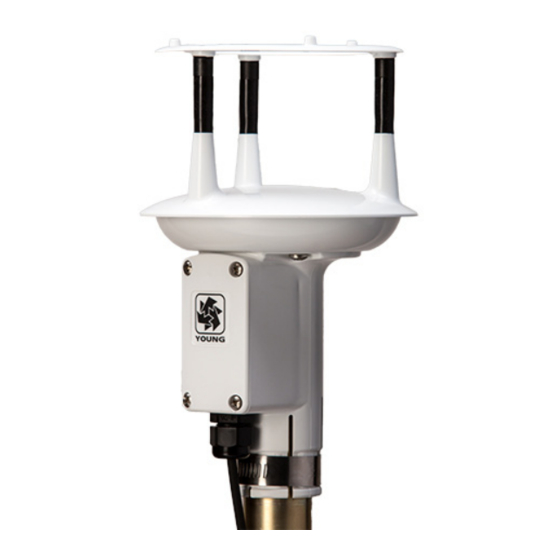
- Page 1 METEOROLOGICAL INSTRUMENTS INSTRUCTIONS ResponseONE MODEL 91000 ULTRASONIC ANEMOMETER R.M. YOUNG COMPANY 2801 AERO PARK DRIVE, TRAVERSE CITY, MICHIGAN 49686, USA TEL: (231) 946-3980 FAX: (231) 946-4772 WEB: www.youngusa.com PN: 91000-90 REV: B021918...
-
Page 2: Table Of Contents
OPERATING INSTRUCTIONS Model 91000 ResponseONE Ultrasonic Anemometer Contents SECTION DESCRIPTION PAGE INTRODUCTION ......................... 1 SPECIFICATIONS ....................... 1 BEFORE INSTALLATION ....................2 INSTALLATION ........................2 Placement ..........................2 Mounting and Alignment ...................... 2 Wiring Connections ......................3 OPERATION ........................3 Serial Output Formats ......................3 SDI-12 Measurement Commands .................. -
Page 4: Introduction
Continuous serial output or polled operation may be used. RS-232 or RS-485 serial format options allows direct connection to YOUNG displays, marine NMEA systems, data loggers, or other compatible serial devices. Operating parameters are easily reviewed and changed using the ResponseONE CONFIG program available for download at www. -
Page 5: Before Installation
Locate damage to your YOUNG supplier. Be sure to retain the bird spikes the sensor well away from obstructions. As a general rule, air flow and orientation ring for use. -
Page 6: Wiring Connections
4.2.2 ORIENTATION USING BUILT-IN ELECTRONIC COMPASS. Note: Acclimate the ResponseONE to ambient temperature at the installation site before calibrating. Place ResponseONE sensor on mounting pipe, fully seating it on the pipe and allowing for free rotation of the sensor. Connect cable as indicated in APPENDIX A and apply power to the system. -
Page 7: Sdi-12 Measurement Commands
RMYT is a 6-byte binary data format sent at 9600 baud using RS-485 the measurement is ready, and data values will be available. The OUTPUT ONLY mode. It is for use with the YOUNG Model 06201 Wind Tracker. maximum time ranges from 1 to 5 seconds depending on the Sample Count. -
Page 8: Extended Commands
RESPONSE DESCRIPTION aXCE,ERR CE=0/1 ONLY<CR><LF> a<CR><LF> Address Query a<CR><LF> Acknowledge Active aXCDnddmm! nddmm = Declination (n=E/W/0,dd=DEG, a13 YOUNG C091000 vvvnnnnnn<CR><LF> mm=MIN) aXCD,CD=nddmm<CR><LF> Send Identification aXCD,ERR CD=nddmm n=E/W/0, dd=00- vvv = Firmware Version 90, mm=00-60 ONLY<CR><LF> nnnnnn = Serial Number aAb! b<CR><LF>... -
Page 9: Setting Serial Outputs And Operating Parameters
6.1 SENSOR CONFIGURATION WITH ResponseONE CONFIG sending simple text commands. The following guidelines apply: PROGRAM (RECOMMENDED) The YOUNG ResponseONE CONFIG program is available from the The YOUNG sensor and communication program must operate at factory web site: www.youngusa.com. It provides an easy method the same baud rate and be properly connected. -
Page 10: Command Overview
Usage example: IMPORTANT NOTE: >SET044 Sets wind speed to m/s. The YOUNG ResponseONE CONFIG program automatically saves all settings to flash memory when they are sent to the SET05a Set sensor address for ASCII POLLED and sensor. Settings that are changed manually must be saved to SDI-12. - Page 11 SET10nnnn Set output interval. Sets the time interval between measurements in one millisecond increments. Lower values increase power consumption when continuous measurements are taken. Default is 1000. Where nnnn= 0000-9999 Usage example: >SET101000 Sets output interval to 1000 milliseconds (1 second) (Note: If output interval is set too low, the ResponseONE will automatically calculate the minimum output interval.) SET12nnn...
-
Page 12: Example Settings
12 months from date of initial purchase. setup parameters. See wiring diagrams for jumper settings. Liability is limited to repair or replacement of the defective item. A copy of the warranty policy may be obtained from R. M. Young Company. 7.1 FACTORY DEFAULT RS-232... -
Page 13: Wiring Connections
Set connected device baud rate to match ResponseONE . Serial Device 1 start bit, 8 data bits, no parity, 1 stop bit, no flow control. Use shielded cable. Connect cable shield to earth ground as shown. (Color code is for Young 18446 cable) 92000 RESPONSE ONE Typical DB-9... -
Page 14: A3: Rs-485 / Rs-422 Serial Connection - Half Duplex
Serial Device 1 start bit, 8 data bits, no parity, 1 stop bit, no flow control. Use shielded cable. Connect cable shield to earth ground as shown. (Color code is for Young 18446 Cable) Sensor TX/RX (Inverted signal) Z.SDI JUMPER Sensor TX/RX (Non-inverted signal) TX.B... -
Page 15: A5: Sdi-12 Serial Connection
1200, 4800, 9600, 19200 or 38400 Set 26800 Translator baud rate to match ResponseONE . Model 26800 Translator Use shielded cable. Connect cable shield to earth ground as shown. (Color code is for Young 18660 cable) JUMPER SHIELD Earth Z.SDI... -
Page 16: A7: 06201 Wind Tracker Wiring Connections
Output Format: RMYT Baud Rate: 9600 These are the default sensor settings as shipped unless otherwise requested. Use shielded cable. Connect cable shield to earth ground as shown. (Color code is for Young 18446 Cable) ALARM V OUT JUMPER JUMPER Z.SDI... -
Page 17: Sensor Orientation And Dimensions
APPENDIX B: SENSOR ORIENTATION AND DIMENSIONS APPENDIX B: SENSOR ORIENTATION AND DIMENSIONS EXAMPLE: "WIND AT 45° " 0° 90° 270° 180° JUNCTION POLAR (WIND SPEED, WIND DIRECTION) 135 mm +V m/s "WIND FROM NORTH" 220 mm +U m/s "WIND FROM EAST" MOUNTING PIPE INSERTION... -
Page 18: Troubleshooting
APPENDIX C: TROUBLESHOOTING Problem Solution No Output • Check input voltage at sensor (10 – 30 VDC). • Check wiring connections. • Verify serial settings (baud rate, 1 stop bit, 8 data bits, no parity, no flow control). • ‘Acquire’ the sensor with the ResponseONE CONFIG program (see section 6.2) and verify setup mode.
Need help?
Do you have a question about the ResponseONE 91000 and is the answer not in the manual?
Questions and answers