Advertisement
• When connecting the GP37W2-BG41-24V(hereafter referred to as the
"GP")'s power cord terminals to the power terminal block, check first
that the GP power supply is completely turned OFF, via a breaker, or
similar unit.
• Do not use power beyond the GP's specified voltage range. Doing so
may cause a fire or an electric shock.
• Do not modify the GP's design, since it may lead to a fire or an electric
shock.
• Do not use the GP in an environment where flammable gases are
present, since operating the GP may cause an explosion.
• If the GP's lithium battery
are reversed), it may explode. Therefore, please contact your local GP
distributor prior to changing the battery.
• Do not use GP touch panel switches in life-threatening or important
disaster prevention situations. For safety related switches, such as
an emergency stop switch, be sure to use a separate mechanical switch.
• To prevent operator injury or machine damage, be sure to design your
system so that machinery will not malfunction due to a communication
fault between the GP and its host controller.
• The GP is not appropriate for use with aircraft control devices, aerospace
equipment, central trunk data trans-mission (communication) devices,
nuclear power control devices, or medical life support equipment, due to
these devices inherent requirements of extremely high levels of safety
and reliability.
• When using the GP with transportation vehicles (trains, cars and ships),
disaster and crime prevention devices, various types of safety equipment,
non-life support re-lated medical devices, etc. redundant and/or failsafe
sys-tem designs should be used to ensure the proper degree of reliability
and safety.
GP Usage Cautions
• To prevent touch panel damage, do not strike the panel face with a
hard or heavy object, or push hard on the panel face.
• Do not install the GP where the temperature will exceed its specified range.
• Do not allow water, liquids or metal particles to enter the GP. Any of
these can lead to a malfunction or short circuit.
• Avoid installing the GP where sudden, large changes in temperature
may occur. These changes may cause condensation to form inside
the unit, possibly causing the GP to malfunction.
• Do not install the GP where its ventilation holes may be blocked. If
these holes are blocked, excessive heat will build up inside the GP.
• Do not install or store the GP :
- Where high levels of dust exist or in direct sunlight.
- Where either strong shocks or excessive vibration may occur.
- Where chemicals or chemical fumes are present.
- Near high temperature equipment.
• Do not use paint thinner or organic solvents to clean the GP's case or
screen.
• Be sure to back up all GP data regularly.
• After turning the GP OFF, be sure to wait a few seconds before turning
it ON again. If the GP is re-started too quickly, it may not start up cor-
rectly.
*1
WARNINGS
*1
is incorrectly replaced (i.e. its + and – sides
This mark is applicable only in Taiwan.
Advertisement
Table of Contents

Related Manuals for Pro-face GP37W2-BG41-24V


Summary of Contents for Pro-face GP37W2-BG41-24V
- Page 1 WARNINGS • When connecting the GP37W2-BG41-24V(hereafter referred to as the "GP")'s power cord terminals to the power terminal block, check first that the GP power supply is completely turned OFF, via a breaker, or similar unit. • Do not use power beyond the GP's specified voltage range. Doing so may cause a fire or an electric shock.
-
Page 2: Ul/C-Ul (Csa) Application Notes
UL/c-UL (CSA) Application Notes The GP37W2-BG41-24V is a UL/c-UL (CSA) recognized product. (UL File No. E177793.) This unit conforms as a component to the following standards: UL 1950, Third Edition, dated July 26,1995 (Standard for Safety of Information Technology Equipment, including Electrical Business Equipment) CAN/CSA-C22.2, No.950-95... - Page 3 CNS Application Notes The GP37W2-BG41-24V complies with the following CNS recognized standard. CNS 13438 (Class A device) The GP is an Industrial Device (Class A Device). Use of this device in a home may cause radio wave interference with nearby devices. If interference does occur, please try a variety of...
-
Page 4: Package Contents
Revision Information Revision information can be found on your GP unit’s rear-face Pro-face label. The bot- tom-most [REV] row’s asterisk (*) mark indicates the Revision character. In the example shown below, the asterisk indicates that this unit’s Revision character is “D”. -
Page 5: Parts Names And Functions
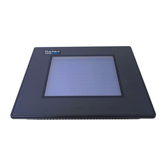
Parts Names and Functions A: Display Displays User-created screens and host (PLC) data. GP37W2-BG41-24V Blue mode LCD B: Touch Panel Performs screen change operations and sends data to the host (PLC). C: Power Lamp Lights when the power cord is connected. -
Page 6: Serial Interface
Serial Interface This interface is used to connect the GP to the host (PLC), via either an RS-232C or RS-422 cable. Pin # Signal Name Meaning Frame Ground Send Data (RS-232C) Receive Data (RS-232C) Request to Send (RS-232C) Clear to Send (RS-232C) No Connection Signal Ground Carrier Detect (RS-232C) - Page 7 • Use pins 23(BUZZ GND) and 25(BUZZ OUT) when producing external output for an alarm. This output circuit does not contain fuses. If used, Pro-face recommends the design of an external safety circuit. (GP units Revision P or later) To confirm your GP unit’s Revision, refer to "Revision Information".
-
Page 8: Installation
Installation Confirm the Installation Gasket's Positioning It is strongly recommended that you use the gasket since it absorbs vibration in addi- tion to repelling water. Prior to installing the GP in its metal panel, place the unit on a level surface with the display panel facing downward and check that the installation gasket is securely attached to the back of the unit. - Page 9 Wiring WARNINGS WARNINGS • To avoid an electric shock, check first that the GP's power supply is completely turned OFF, via a breaker, or similar unit when connecting the GP power cord terminals to the power terminal block. • GP-37W2B Series units are designed to use only DC24V in- put.
- Page 10 Connecting the GP's Power Cord When connecting the power cord, be sure to follow the procedures given below. 1. Confirm that the GP's Power Cord is unplugged from the power supply. 2. Use a screwdriver to remove the Power Input Terminal Block's clear plastic cover. 3.
Need help?
Do you have a question about the GP37W2-BG41-24V and is the answer not in the manual?
Questions and answers