
Related Manuals for trig TT31


Summary of Contents for trig TT31
- Page 1 TT31 Mode S Transponder Installation Manual 00455-00-AJ 1 February 2010 Trig Avionics Limited Heriot Watt Research Park Riccarton, Currie EH14 4AP Scotland, UK Copyright Trig Avionics Limited, 2009, 2010...
- Page 2 This page intentionally left blank...
-
Page 3: Table Of Contents
TT31 Transponder Installation Manual 1 February 2010 00455-00 Issue AJ CONTENTS PREFACE ............................1 ............................ 1 URPOSE ............................1 COPE ....................1 HANGES FROM REVIOUS SSUE ....................1 OCUMENT ROSS EFERENCES INTRODUCTION .......................... 2 TT31 D ........................2 ESCRIPTION ..........................2 NTERFACES TECHNICAL SPECIFICATIONS .................... - Page 4 TT31 Transponder Installation Manual 1 February 2010 00455-00 Issue AJ 5.5.10 GPS Position Input ......................11 5.5.11 TIS Traffic Output......................12 ..................... 12 OLEX RIMP ERMINALS ......................12 NTENNA NSTALLATION 5.7.1 Antenna Cable ........................ 13 5.7.2 BNC Connector....................... 15 / BNC C ..................
- Page 5 TT31 Transponder Installation Manual 1 February 2010 00455-00 Issue AJ ..........................24 TOPWATCH ADS-B P ....................24 OSITION ONITOR ....................... 25 LTITUDE ONITOR 8.10 ......................25 AULT NNUNCIATION 8.11 ..................... 25 EMPERATURE PERATION CONTINUED AIRWORTHINESS .................... 26 LIMITED WARRANTY ......................27 ENVIRONMENTAL QUALIFICATION FORM..............
- Page 6 TT31 Transponder Installation Manual 1 February 2010 00455-00 Issue AJ This page intentionally left blank ______________________ Trig Avionics Limited...
-
Page 7: Preface
This document applies to the installation of the TT31 Mode S Transponder. At the publication date of this manual the software version identifier for the TT31 is 2.5 and the FPGA version identifier is 231006a. The software and FPGA versions are subject to change without notice. -
Page 8: Introduction
2. Introduction 2.1 TT31 Description The TT31 Mode S panel mount transponder is an ED-73B Class 1 compliant Mode S level 2es datalink transponder, with support for extended squitter, elementary surveillance and SI codes. The TT31 is also a DO-260A change 2 Class B0 compliant ADS-B out participant, which also meets the power output levels for Class B1. - Page 9 TT31 Transponder Installation Manual 1 February 2010 00455-00 Issue AJ TIS Output RS232 output for connection to traffic display. ______________________ Trig Avionics Limited Page 3...
-
Page 10: Technical Specifications
2.8lbs. (1.35Kg) 3.3 Installation Approval The conditions and tests required for the TSO approval of the TT31 Mode S Transponder are minimum performance standards. It is the responsibility of those desiring to install this transponder on or within a specific type or class of aircraft to determine that the aircraft operating conditions are within the TSO standards. -
Page 11: Unit And Accessories Supplied
TT31 Pilots Operating Manual 00454-00 4.4 Required Items Additional items you will require, but which are not in the TT31 package, include: Antenna and fixing hardware. The TT31 is compatible with any transponder antenna approved to ETSO C74 or 2C112. - Page 12 TT31 Transponder Installation Manual 1 February 2010 00455-00 Issue AJ Altitude encoder. You require an encoding altimeter or a blind encoder with either parallel Gray code or RS232 serial output. For best results, and simpler installation, an encoder with a serial output is recommended.
-
Page 13: Installation
Select a position in the panel that is not too close to any high external heat source. (The TT31 is not a significant heat source itself and does not need to be kept away from other devices for this reason). -
Page 14: Primary Interface - Pinout
TT31 Transponder Installation Manual 1 February 2010 00455-00 Issue AJ 5.4.1 Primary Interface – Pinout Signal Direction Ground Lighting 14V Input Lighting 28V Input Suppress I/O * Bi-directional Squat Switch In * Input Serial Alt Out * Output Serial Alt In *... -
Page 15: Secondary Interface - Pinout
TT31 Transponder Installation Manual 1 February 2010 00455-00 Issue AJ 5.4.2 Secondary Interface - Pinout Signal Direction Ground TIS Traffic Out Output GPS Position In Input Reserved Input Audio Mute In Input Altitude Alert Output Ground Audio + Output Audio -... -
Page 16: Interface Details
The Suppress I/O on contact 4 is an ARINC compatible suppression bus interface, which acts as both a input and an output. The TT31 will assert this signal when it is transmitting, and can be suppressed by other equipment that asserts the signal. The TT31 will drive approximately 24 Volts on the output (independently of supply voltage), and will treat the input as active whenever the bus has greater than 10 Volts. -
Page 17: Ident Switch Input
5.5.9 Altitude Alerter Output The TT31 includes an altitude monitor function that can alert the pilot to altitude deviations in cruise flight. The altitude alerter output, on the 12 way secondary connector, is switched to ground when th altitude deviation is detected and can be connected to a warning light or soun der to warn the pilot. -
Page 18: Tis Traffic Output
Traffic Information Service messages. It is an RS232 output on the 12 way secondary connector. The TT31 TIS output can drive the Trig proprietary traffic protocol, and can also support the format used by certain Garmin handheld displays, including the 495, 496, 695 and 696. -
Page 19: Antenna Cable
5.7.1 Antenna Cable The TT31 is designed to meet Class 1 requirements with an allowance of 2 dB for loss in the connector and cable used to connect it to the antenna. Excessive loss will degrade both transmitter output power and receiver sensitivity. -
Page 20: Trig Avionics Limited
TT31 Transponder Installation Manual 1 February 2010 00455-00 Issue AJ Allow minimum sepa rati on of 300mm (1 2 in ches) from an ADF enna cable p the ca ble run a s short as possible Avoid routing the cable round t ight bends. -
Page 21: Bnc Connector
TT31 Transponder Installation Manual 1 February 2010 00455-00 Issue AJ 5.7.2 BNC Connector This section describes the technique for attaching the antenna cable to the supplied blind-mate BNC connector. If a low-loss cable is needed that has too large a dielectric diameter to fit the supplied blind-mate BNC connector, a short length (up to 150mm or 6 inches) of smaller cable may be used with suitable mating connectors to adapt to the transponder connector. -
Page 22: Tray / Bnc Connector Assembly
TT31 Transponder Installation Manual 1 February 2010 00455-00 Issue AJ Slide heat shrink tubing forward (flush to connector) and heat to shrink the tubing. Complete the assembly by installing the bushing over the centre contact, and fitting the cap. -
Page 23: Trig Avionics Limited
TT31 Transponder Installation Manual 1 February 2010 00455-00 Issue AJ When the BNC is prepared, feed it through the TT31 mounting tray and attach the washer combination in the following order: Wave washer (p/n 00317-00). 00239-00 Plain washer (p/n 00241-00). -
Page 24: Installation Setup And Test
Issue AJ 6. Installation Setup and Test The TT31 uses a simple setup system to program important system parameters, including the Mode S address. In the original factory configuration, the setup screen is the first thing that runs when you switch on the transponder. -
Page 25: Airspeed Category
Freeflight 1201 and NexNav 3101 GPS receivers generally run at 19200 bps. Note: The TIS output and GPS input speeds are not separately controlled on the TT31. Not all combinations of GPS input and TIS output will be usable if the external devices operate on fixed bit rates and are different to each other. -
Page 26: Aircraft Length And Width
On the ground, ADS-B transmits encoded aircraft size information which is used by ATC to identify taxiing routes and potential conflicts. When configured for ADS-B, the TT31 will ask for the aircraft length and width (wingspan), in metres, and will calculate the appropriate size code for transmission. -
Page 27: Test Items
TT31 Transponder Installation Manual 1 February 2010 00455-00 Issue AJ 6.2 Test items 6.2.1 Interface Check The Interface Check screen displays the current state of the external IDENT, external STANDBY and external GROUND inputs. Exercise these inputs to confirm the correct behaviour. -
Page 28: Post Installation Checks
TT31 Transponder Installation Manual 1 February 2010 00455-00 Issue AJ 7. Post Installation Checks Post installation checks should be carried out in accordance with your certification requirements. These checks should include: Mode S interrogations to verify correct address programming. -
Page 29: Normal Operation
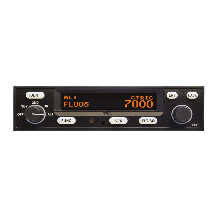
TT31 Transponder Installation Manual 1 February 2010 00455-00 Issue AJ 8. Normal Operation 8.1 Overview On the front panel is an amber backlit LCD display flanked by a rotary mode selector knob (OFF, SBY, GND, ON, and ALT) and a continuously rotating knob used for code and data entry. -
Page 30: Push Buttons
TT31 Transponder Installation Manual 1 February 2010 00455-00 Issue AJ 8.4 Push Buttons IDENT Press the IDENT button when ATC instructs you to “Ident” or “Squawk Ident”. This activates the SPI pulse in the transponder replies for 18 seconds. IDENT will appear in the display. -
Page 31: Altitude Monitor
No replies will be made to interrogations when a fault is detected. 8.11 Low Temperature Operation The TT31 is certified for correct operation at temperatures down to -20 Celsius. At low temperatures however the display performance will be impaired. The aircraft cockpit should be warmed to allow normal operation of the transponder before takeoff. -
Page 32: Continued Airworthiness
Issue AJ 9. Continued Airworthiness Other than for periodic functional checks required by the regulations, the TT31 Mode S transponder has been designed and manufactured to allow “on condition maintenance”. This means that there are no periodic service requirements necessary to maintain continued airworthiness, and no maintenance is required until the equipment does not properly perform its intended function. -
Page 33: Limited Warranty
Issue AJ 10. Limited Warranty Trig Avionics Limited warrants our products to be free from defects in materials and workmanship for a period of two (2) years from the date of installation by an authorised dealer. This warranty covers repair and/or replacement at our option, of any parts found to be defective, provided such defects in our opinion are due to faulty material or workmanship and are not caused by tampering, abuse, or normal wear. -
Page 34: Environmental Qualification Form
TT31 Transponder Installation Manual 1 February 2010 00455-00 Issue AJ 11. Environmental Qualification Form Nomenclature TT31 Mode S Transponder Part Number: 00220-(XX) ETSO: 2C112b Manufacturer Trig Avionics Limited Address Heriot Watt Research Park, Riccarton, Currie, Scotland, EH14 4AP Conditions DO-160D... -
Page 35: Trig Avionics Limited
TT31 Transponder Installation Manual 1 February 2010 00455-00 Issue AJ Because the ETSO for ADS-B was published later than the ETSO for transponders it refers to a later edition of the environmental standard, ED-14E/DO-160E, rather than ED-14D/DO-160D. The following form provides the environmental data in DO-160E format. The two tables are equivalent. -
Page 36: Ads-B Compliance
12. ADS-B Compliance TT31 transponders with software version 2.3 and above include support for Extended Squitter ADS-B out. The TT31 is a DO-260A change 2 compliant category B0 broadcast-only participant, which also meets the power output levels for category B1. -
Page 37: Amc 20-24 Compliance
ADS-B output system in the transponder. At the publication date of this manual, the only commercially available GPS receivers we are aware of that can be used with the TT31 to meet the system requirements of AMC20-24 are the Freeflight 1201 and the NexNav 3101. -
Page 38: Installation Drawings
TT31 Transponder Installation Manual 1 February 2010 00455-00 Issue AJ 13. Installation Drawings All dimensions in millimetres ______________________ Page 32 Trig Avionics Limited... -
Page 39: Basic Interconnect Diagram
TT31 Transponder Installation Manual 1 February 2010 00455-00 Issue AJ 14. Basic Interconnect Diagram ______________________ Trig Avionics Limited Page 33... -
Page 40: Trig Avionics Limited
TT31 Transponder Installation Manual 1 February 2010 00455-00 Issue AJ This page intentionally left blank ______________________ Page 34 Trig Avionics Limited...
Need help?
Do you have a question about the TT31 and is the answer not in the manual?
Questions and answers