
Related Manuals for trig TT31


Summary of Contents for trig TT31
-
Page 1: Installation Manual
TT31 Mode S Transponder Installation Manual 00455-00-AQ 8 May 2017 Trig Avionics Limited Heriot Watt Research Park Riccarton, Currie EH14 4AP Scotland, UK Copyright Trig Avionics Limited 2006 - 2017... - Page 2 This page intentionally left blank...
-
Page 3: Table Of Contents
TT31 Transponder Installation Manual 8 May 2017 00455-00 Issue AQ CONTENTS PREFACE ............................1 ............................ 1 URPOSE ............................1 COPE ....................1 HANGES FROM REVIOUS SSUE ....................1 OCUMENT ROSS EFERENCES INTRODUCTION .......................... 2 TT31 D ........................2 ESCRIPTION ..........................2 NTERFACES TECHNICAL SPECIFICATIONS .................... - Page 4 TT31 Transponder Installation Manual 8 May 2017 00455-00 Issue AQ 5.7.3 Mutual Suppression ......................15 5.7.4 Serial Port Options ......................15 5.7.5 Altitude Inputs and Output ....................15 5.7.6 Squat Switch Input ......................16 5.7.7 Ident Switch Input ......................16 5.7.8...
- Page 5 TT31 Transponder Installation Manual 8 May 2017 00455-00 Issue AQ ......................25 ELECTOR ......................... 25 LIGHT IMER ..........................25 TOPWATCH ADS-B P ....................25 OSITION ONITOR ....................... 25 LTITUDE ONITOR 8.10 ..........................26 ARNINGS 8.11 ......................26 AULT NNUNCIATION 8.12 .....................
- Page 6 TT31 Transponder Installation Manual 8 May 2017 00455-00 Issue AQ This page intentionally left blank ______________________ Trig Avionics Limited...
-
Page 7: Preface
This document applies to the installation of the TT31 Mode S Transponder. At the publication date of this manual the software version identifier for the TT31 is 3.15 and the FPGA version identifier is 020714a. The software and FPGA versions are subject to change without notice. -
Page 8: Introduction
2. Introduction 2.1 TT31 Description The TT31 Mode S panel mount transponder is an ED-73B Class 1 compliant Mode S level 2es datalink transponder, with support for extended squitter, elementary surveillance and SI codes. The TT31 is also a DO-260B Class B1S compliant ADS-B out participant. The TT31 meets the relevant environmental requirements of ED-14D, and is certified to ETSO 2C112b, ETSO C166a, TSO C112 and TSO C166b. - Page 9 TT31 Transponder Installation Manual 8 May 2017 00455-00 Issue AQ 2 x RS232 Inputs Connections to an external RS232 GPS receiver for ADS-B support and/or a serial altitude encoder or air data computer. Using serial altitude data allows the transponder to report altitude with 25 foot resolution.
-
Page 10: Technical Specifications
2.8lbs. (1.35Kg) 3.3 Installation Approval The conditions and tests required for the TSO approval of the TT31 Mode S Transponder are minimum performance standards. It is the responsibility of those desiring to install this transponder on or within a specific type or class of aircraft to determine that the aircraft operating conditions are within the TSO standards. -
Page 11: Mode S Transponder Installation Approval
Issue AQ 3.3.1 Mode S Transponder Installation Approval Installation of the TT31 as a replacement for an existing transponder is considered a Minor Change by EASA and the FAA, and should be documented accordingly. Note: With no GPS interface configured, the transponder does not enable any ADS-B functions, and will behave as a conventional Mode S transponder. -
Page 12: Unit And Accessories Supplied
TT31 Pilots Operating Manual 00454-00 4.4 Required Items Additional items you will require, but which are not in the TT31 package, include: • Antenna and fixing hardware. The TT31 is compatible with any transponder antenna approved to (E)TSO C74 or C112. - Page 13 TT31 Transponder Installation Manual 8 May 2017 00455-00 Issue AQ you may need to fabricate additional brackets to support the transponder tray. To support the optional ADS-B features a GPS receiver with an appropriate serial output is required. To support the optional TIS features a display with an appropriate serial or ARINC 429 input is required.
-
Page 14: Installation
• Select a position in the panel that is not too close to any high external heat source. (The TT31 is not a significant heat source itself and does not need to be kept away from other devices for this reason). -
Page 15: Primary Interface - Pinout
TT31 Transponder Installation Manual 8 May 2017 00455-00 Issue AQ 5.4.1 Primary Interface – Pinout Signal Direction Ground Lighting 14V Input Lighting 28V Input Suppress I/O * Bi-directional Squat Switch In * Input RS232 Output 1 * Output RS232 Input 1 *... -
Page 16: Secondary Interface - Pinout
TT31 Transponder Installation Manual 8 May 2017 00455-00 Issue AQ 5.4.2 Secondary Interface - Pinout Signal Direction Ground RS232 Output 2 Output RS232 Input 2 Input Reserved Input Audio Mute In Input Altitude Alert Output Ground Audio + Output Audio -... -
Page 17: Molex Crimp Terminals
RF energy is radiated inside the aircraft. 5.5.1 Antenna Cable The TT31 is designed to meet Class 1 requirements with an allowance of 2 dB for loss in the connectors and cable used to connect it to the antenna. Excessive loss will degrade both transmitter output power and receiver sensitivity. -
Page 18: Bnc Connector
TT31 Transponder Installation Manual 8 May 2017 00455-00 Issue AQ • Has less than 1.5dB loss for the run length needed • Has a characteristic impedance of 50 Ohms • Has double braid screens or has a foil and braid screen Once the cable run length is known, a cable type with low enough loss per metre that meets the above requirements can be chosen. - Page 19 TT31 Transponder Installation Manual 8 May 2017 00455-00 Issue AQ Dimension Cut size Cut size (mm) (inches) 12.7 0.25 0.125 • Insert the cable into the connector – the inner conductor should align with the centre contact, the inner shield should be inside the body of the connector and the outer shield should be outside the body.
-
Page 20: Tray / Bnc Connector Assembly
TT31 Transponder Installation Manual 8 May 2017 00455-00 Issue AQ 5.6 Tray / BNC Connector Assembly When the BNC is prepared, feed it through the TT31 mounting tray and attach the washer combination in the following order: • Wave washer (p/n 00317-00). 00239-00 •... -
Page 21: Interface Details
Mode S interrogations, whereas parallel Gray code format can only represent altitude to the nearest 100 feet. You must choose between serial or parallel formats – you should NOT connect both. If a parallel encoder is connected the TT31 will always use that as the altitude source even if a serial encoder is also connected. -
Page 22: Squat Switch Input
The TT31 can also accept Shadin family Format G, Format S and Format Z air data protocols which supply both altitude and airspeed information. The airspeed information can be used to provide an automatic air/ground determination for an ADS-B installation. -
Page 23: Altitude Alerter Output
5.7.11 Altitude Alerter Output The TT31 includes an altitude monitor function that can alert the pilot to altitude deviations in cruise flight. The altitude alerter output, on the 12 way secondary connector, is switched to ground when the altitude deviation is detected and can be connected to a warning light or sounder to warn the pilot. -
Page 24: Installation Setup And Test
Issue AQ 6. Installation Setup and Test The TT31 uses a simple setup system to program important system parameters, including the Mode S address. In the original factory configuration, the setup screen is the first thing that runs when you switch on the transponder. -
Page 25: Vfr Squawk Code
6.1.8 RS232 Input/Output There are two RS232 input lines and two RS232 output lines on the TT31. Either input can be used to receive data from a serial altitude source, such as an altitude encoder or air data computer, or a GPS position source for ADS-B. -
Page 26: Ads-B Configuration
00455-00 Issue AQ Trig TN72 TABS GPS receiver also runs at 9600 bps, and panel mount GPS units with Aviation format outputs generally run at 9600 bps. NMEA GPS units generally run at 4800 bps. The Trig TN70 GPS receiver runs at 19200 bps, as does the FreeFlight 1201 and similar devices. -
Page 27: Audio Volume
On the ground, ADS-B transmits encoded aircraft size information which is used by ATC to identify taxiing routes and potential conflicts. When configured for ADS-B, the TT31 will ask for the aircraft length and width (wingspan), in metres, and will calculate the appropriate size code for transmission. -
Page 28: Altitude Check
TT31 Transponder Installation Manual 8 May 2017 00455-00 Issue AQ external GROUND inputs. Exercise these inputs to confirm the correct behaviour. 6.2.2 Altitude Check The Altitude check displays the current state of the altitude inputs. Individual Gray code lines are shown to assist in fault tracing. -
Page 29: Post Installation Checks
TT31 Transponder Installation Manual 8 May 2017 00455-00 Issue AQ 7. Post Installation Checks Post installation checks should be carried out in accordance with your certification requirements. These checks should include: • Mode S interrogations to verify correct address programming. -
Page 30: Normal Operation
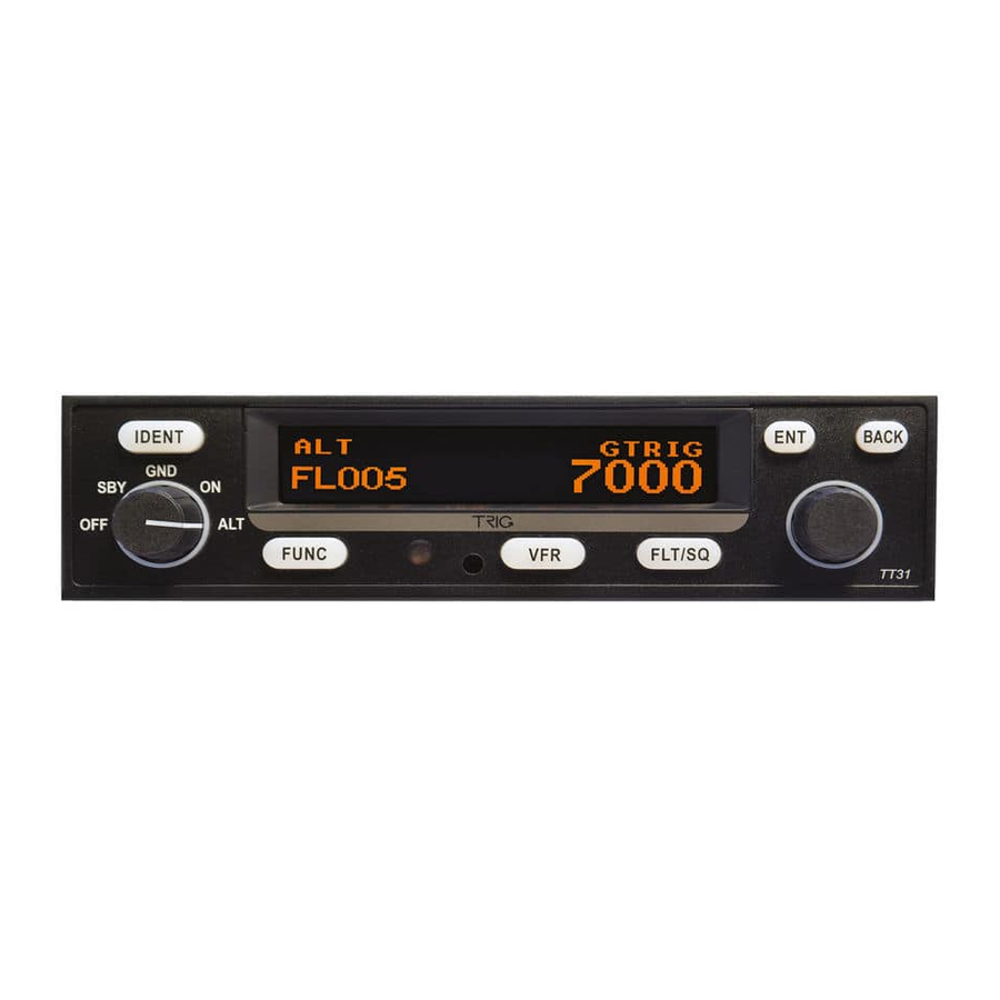
TT31 Transponder Installation Manual 8 May 2017 00455-00 Issue AQ 8. Normal Operation 8.1 Overview On the front panel is an amber backlit LCD display flanked by a rotary mode selector knob (OFF, SBY, GND, ON, and ALT) and a continuously rotating knob used for code and data entry. -
Page 31: Push Buttons
TT31 Transponder Installation Manual 8 May 2017 00455-00 Issue AQ 8.4 Push Buttons Press the IDENT button when ATC instructs you to “Ident” or “Squawk Ident”. This IDENT activates the SPI pulse in the transponder replies for 18 seconds. IDENT will appear in the display. -
Page 32: Warnings
8.12 Low Temperature Operation The TT31 is certified for correct operation at temperatures down to -20 Celsius. At low temperatures however the display performance will be impaired. The aircraft cockpit should be warmed to allow normal operation of the transponder before takeoff. -
Page 33: Continued Airworthiness
9. Continued Airworthiness 9.1 Maintenance Other than for periodic functional checks required by the regulations, the TT31 Mode S transponder has been designed and manufactured to allow “on condition maintenance”. This means that there are no periodic service requirements necessary to maintain continued airworthiness, and no maintenance is required until the equipment does not properly perform its intended function. -
Page 34: Limited Warranty
Heriot Watt Research Park Riccarton, Edinburgh, EH14 4AP Trig Avionics will not accept or pay for any charges for warranty work performed outside our factory without prior written consent. This warranty applies only to products in normal use. It does not apply to units or circuit boards... -
Page 35: Environmental Qualification Form
TT31 Transponder Installation Manual 8 May 2017 00455-00 Issue AQ 11. Environmental Qualification Form Nomenclature TT31 Mode S Transponder Part Number: 00220-(XX) ETSO: 2C112b Manufacturer Trig Avionics Limited Address Heriot Watt Research Park, Riccarton, Currie, Scotland, EH14 4AP Conditions DO-160D... - Page 36 TT31 Transponder Installation Manual 8 May 2017 00455-00 Issue AQ Because the ETSO for ADS-B was published later than the ETSO for transponders it refers to a later edition of the environmental standard, ED-14E/DO-160E, rather than ED-14D/DO-160D. The following form provides the environmental data in DO-160E format. The two tables are equivalent.
-
Page 37: Ads-B Compliance
TT31 transponders with software version 3.1 and above include support for Extended Squitter ADS-B out which is compliant with DO-260B. The TT31 is a B1S ADS-B transmitter. 12.1 ADS-B Parameters Supported The following table lists the ADS-B parameters that are transmitted by the TT31 transponder when connected to an appropriate GPS receiver. Parameter... -
Page 38: Cs-Acns Compliance
ADS-B (Avi) Trig ADSB Garmin GPS 20A Garmin ADSB 12.3 CS-ACNS Compliance The TT31 transponder can be connected to the following GPS units to form the basis of a CS-ACNS compliant ADS-B installation: GPS Unit GPS Output Setting TT31 Input Setting... -
Page 39: Automatic Air/Ground Determination
The TT31 will transmit ground speed and ground track within a surface ADS-B message. The TT31 will suppress the ground track at velocities less than 7 knots. • When using the GPS listed in the table above, the TT31 will set SIL = 3 and SIL = 0. For SUPP TSO-C199 TABS GPS the TT31 will set SIL = 1 and SIL = 0. -
Page 40: Installation Drawings
TT31 Transponder Installation Manual 8 May 2017 00455-00 Issue AQ 13. Installation Drawings All dimensions in millimetres ______________________ Page 34 Trig Avionics Limited... -
Page 41: Connection Diagrams
TT31 Transponder Installation Manual 8 May 2017 00455-00 Issue AQ 14. Connection Diagrams 14.1 Master Drawing List Figure 14-A Typical TT31 Interconnect ........................................36 Figure 14-B Typical TT31 ADS-B Out Interconnect ....................................36 Figure 14-C RS-232 GPS Interconnect ........................................36 ______________________ Trig Avionics Limited Page 35... - Page 42 Circuit Breaker RS232 Out 2 RS232 In 2 ARINC Traffic B AUDIO PANEL ARINC Traffic A Audio + Audio + Audio - Audio - Audio Mute Coax Antenna Connection Figure 14-A Typical TT31 Interconnect ______________________ Page 36 Trig Avionics Limited...
- Page 43 Aircraft Squat Switch RS232 In 1 Power In CIRCUIT BREAKER Secondary RS232 In 2 Power In Ground Ground GPS POSITION SOURCE RS232 Out Ground Figure 14-B Typical TT31 ADS-B Out Interconnect Coax Antenna GPS ANTENNA ______________________ Trig Avionics Limited Page 37...
- Page 44 TT31 Transponder Installation Manual 8 May 2017 00455-00 Issue AQ GPS POSITION SOURCE TRIG TT31 TT31 TT31 Trig TN72 Trig TN70 NEXNAV MINI FREE FLIGHT GARMIN GARMIN 24-Way 12-Way 1201 500W SERIES 400W SERIES Primary Secondary Connector Connector P5001 P4001...
Need help?
Do you have a question about the TT31 and is the answer not in the manual?
Questions and answers