trig TT21 Installation Manual
Mode s transponder
Hide thumbs
Also See for TT21:
- Operating manual (16 pages) ,
- Installation manual (2 pages) ,
- Installation manual (40 pages)
Table of Contents
Advertisement
Quick Links
Download this manual
See also:
Operating Manual
Advertisement
Table of Contents

Related Manuals for trig TT21


Summary of Contents for trig TT21
- Page 1 TT21/TT22 Mode S Transponder Installation Manual 00560-00-AP 22 August 2017 Trig Avionics Limited Heriot Watt Research Park Riccarton, Edinburgh EH14 4AP Scotland, UK Copyright Trig Avionics Limited, 2013...
- Page 2 This page intentionally left blank...
-
Page 3: Table Of Contents
TT21/TT22 Transponder Installation Manual 22 August 2017 00560-00 Issue AP CONTENTS PREFACE ....................1 ...................1 URPOSE ....................1 COPE ............1 HANGES FROM REVIOUS SSUE ............2 OCUMENT ROSS EFERENCES INTRODUCTION ..................3 TT21/TT22 D ..............3 ESCRIPTION ..................3 NTERFACES 2.2.1 TT21/TT22 Transponder Unit ..........3 2.2.2 TC20 Controller Unit ...............4... - Page 4 ..............12 ONTROLLER OUNTING ...........13 RANSPONDER OUNTING ...............13 OOLING EQUIREMENTS TT21/TT22 T ....14 RANSPONDER LECTRICAL ONNECTIONS TT21/TT22 Interface – Pinout ..........14 5.5.1 TT21/TT22 T ......15 RANSPONDER NTERFACE ETAILS 5.6.1 Power Input ................15 5.6.2 TMAP Bus ................16 5.6.3 Power On ................16 5.6.4 Controller Power ..............16...
- Page 5 TT21/TT22 Transponder Installation Manual 22 August 2017 00560-00 Issue AP ..........20 ONNECTOR RIMP ERMINALS 5.10 ...............21 IRING ONSIDERATIONS 5.11 ..............22 NTENNA NSTALLATION 5.11.1 Antenna Ground Plane............23 5.11.2 Antenna Cable ................24 5.11.3 TNC Connector ..............26 5.12 .............27 TATIC RESSURE ONNECTION INSTALLATION SETUP AND TEST ..........29 ..............29...
- Page 6 TT21/TT22 Transponder Installation Manual 22 August 2017 00560-00 ............34 EST AND ALIBRATION ITEMS 6.2.1 Voltage Check ................34 6.2.2 Altitude Encoder Calibration ..........34 POST INSTALLATION CHECKS ............38 NORMAL OPERATION ..............39 ..................39 VERVIEW ..................39 ISPLAY ..............40 ELECTOR ................40 UTTONS ..............41 ELECTOR ............41...
- Page 7 TT21/TT22 Transponder Installation Manual 22 August 2017 00560-00 Issue AP 12.3 CS-ACNS C ..............54 OMPLIANCE 12.4 TSO C199 TABS C ............55 OMPLIANCE 12.5 ........55 UTOMATIC ROUND ETERMINATION 12.6 ADS-B S ................55 UPPORT INSTALLATION DRAWINGS ............56 13.1 ......56 OUNTING TRAY FIXING AND OVERALL DIMENSIONS 13.2...
- Page 8 TT21/TT22 Transponder Installation Manual 22 August 2017 00560-00 This page intentionally left blank ______________________ Trig Avionics Limited...
-
Page 9: Preface
Transponder. At the publication date of this manual the software version identifier for the TT21 and TT22 is 2.12 and the FPGA version identifier is 1.2. The TC20 controller software version identifier is 1.14. The software and FPGA versions are subject to change without notice. -
Page 10: Document Cross-References
TT21/TT22 Transponder Installation Manual 22 August 2017 00560-00 1.4 Document Cross-References 00559-00 TT21 Mode S Transponder Operating Manual ______________________ Trig Avionics Limited... -
Page 11: Introduction
The TT22 has a nominal power output of 250 watts, and meets the power output requirements for Class 1. The ADS-B function meets DO-260B class B0 for the TT21 and class B1S for the TT22. The TT21/TT22 is certified to ETSO 2C112b and ETSO C166a, and to FAA TSO C112c and C166b. -
Page 12: Tc20 Controller Unit
00560-00 Power Input The TT21/TT22 operates on 11 to 33 Volts DC. Front Panel Datalink A two wire data link is used to connect the TT21/TT22 and the controller. Front Panel Power The controller is powered from the transponder. Remote On/Off The on-off switching is on the controller, and switches this input. -
Page 13: Technical Specifications
TT21/TT22 Transponder Installation Manual 22 August 2017 00560-00 Issue AP 3. Technical Specifications 3.1 TT21 Transponder Unit (00675-00-01) Specification Characteristics Compliance ETSO 2C112b Class 2 Level 2els, ETSO C166a Class B0, TSO C112c Class 2 Level 2els, TSO C166b Class B0... -
Page 14: Tt22 Transponder Unit (00745-00-01)
TT21/TT22 Transponder Installation Manual 22 August 2017 00560-00 Physical Specifications (in the mounting tray) 48mm (1.9”) Height 66mm (2.5”) Width 160mm (6.3”) Length Weight 0.77lbs. (350 g) 3.2 TT22 Transponder Unit (00745-00-01) Specification Characteristics Compliance ETSO 2C112b Class 1 Level 2els, ETSO... -
Page 15: Tc20 Control Unit (00649-00)
TT21/TT22 Transponder Installation Manual 22 August 2017 00560-00 Issue AP Receiver Frequency 1030 MHz Receiver Sensitivity -74dBm ± 3dB Physical Specifications (in the mounting tray) 48mm (1.9”) Height 66mm (2.5”) Width 160mm (6.3”) Length Weight 0.77lbs. (350 g) 3.3 TC20 Control Unit (00649-00) -
Page 16: Installation Approval
22 August 2017 00560-00 3.4 Installation Approval The conditions and tests required for the TSO approval of the TT21/TT22 Mode S Transponder are minimum performance standards. It is the responsibility of those desiring to install this transponder on or within a specific type or class of aircraft to determine that the aircraft operating conditions are within the TSO standards. -
Page 17: Unit And Accessories Supplied
TT21/TT22 Transponder Installation Manual 22 August 2017 00560-00 Issue AP 4. Unit and Accessories supplied 4.1 TT21 Mode S Transponder Items The TT21 Mode S transponder includes the following items: Unit Description Part Number TT21 Mode S Transponder 00675-00-01 TT21/TT22 Mounting Tray 00667-00 4.2 TT22 Mode S Transponder Items... -
Page 18: Required Items
00736-00 Short mounting screws, 4-40 thread 00737-00 4.5 Required Items Additional items you will require, but which are not in the TT21/TT22 package, include: Antenna and fixing hardware. The TT21/TT22 is compatible with any transponder antenna approved to ETSO C74 or 2C112 or... - Page 19 TT21/TT22 Transponder Installation Manual 22 August 2017 00560-00 Issue AP equivalent. Cables. You need to supply and fabricate all required cables. Guidance on cable types is given in section 5 below. Fixings. To secure the transponder tray to the airframe you will need at least 3 flat head screws and three self-locking nuts.
-
Page 20: Installation
The rubber band can be snipped off and discarded when the installation is complete. If you are using the Trig compact cut-out, you do not need the mounting adapters. The controller should be mounted using the four SHORT screws provided. -
Page 21: Transponder Main Unit Mounting
4-40. 5.3 Transponder Main Unit Mounting The TT21/TT22 Mode S transponder is designed to be mounted in any convenient location in the cockpit, the cabin, or an avionics bay. The following installation procedure should be followed, remembering to allow adequate space for installation of cables and connectors. -
Page 22: Tt21/Tt22 Transponder Electrical Connections
5.5 TT21/TT22 Transponder Electrical Connections The TT21/TT22 has a single 25 way female socket which provides the data and power inputs to the transponder. A single TNC coaxial connector attaches to the antenna. -
Page 23: Tt21/Tt22 Transponder Interface Details
The power supply can be 11-33 Volts DC; no voltage adjustment is required. Use a 3 Amp circuit breaker for power supply protection to the TT21/TT22. It is always good practice to use more than one ground wire in an installation. -
Page 24: Tmap Bus
TMAP interface comprises a balanced pair of signals, called A and B, both of which must be connected for communication to work. There are two sets of TMAP pins on the TT21/TT22, TMAP1 A and B, and TMAP2 A and B. This is to support future installation wiring options. The two sets are identical, and either pair (TMAP1 or TMAP2) may be used to connect to the control head. -
Page 25: Ident Switch Input
Issue AP signal when it is transmitting, and can be suppressed by other equipment that asserts the signal. The TT21/TT22 will drive approximately 24 Volts on the output (independently of supply voltage), and will treat the input as active whenever the bus has greater than 10 Volts. -
Page 26: Tis Traffic Output
5.6.10 TIS Traffic Output The TIS traffic is an RS232 output and supports the display of uplinked Traffic Information Service messages. The TT21/TT22 TIS output can drive the Trig proprietary traffic protocol, and can also support the format used by certain Garmin handheld displays, including the 495, 496, 695 and 696. -
Page 27: Tc20 Interface - Pinout
5.8 TC20 Controller Interface Details 5.8.1 TMAP Bus TMAP is a Trig proprietary bus based on RS485 signalling. It provides a bi- directional interface between the transponder and the control head. Each TMAP interface comprises a balanced pair of signals, called A and B, both of which must be connected for communication to work. -
Page 28: Altitude Out
00560-00 TMAP A and B lines on the controller should be connected to the corresponding A and B lines of either TMAP1 or TMAP2 on the TT21/TT22. 5.8.2 Altitude Out The TC20 incorporates an altitude encoder. Certain GPS receivers can benefit from having altitude information supplied to them. -
Page 29: Wiring Considerations
5.10 Wiring Considerations The connection from the TT21/TT22 transponder to the TC20 uses a minimum of six (6) signal lines; the TMAP pair, the Power and Ground pair, and the Remote On discrete line plus associated ground line. In a certified installation the normal wire choice would be Tefzel hook-up wire. -
Page 30: Antenna Installation
TT21/TT22 Transponder Installation Manual 22 August 2017 00560-00 The distance between the TT21/TT22 transponder and the TC20 controller is limited by the impedance of the wire between them. The TC20 is powered from the TT21/TT22, not from aircraft power, and therefore the acceptable voltage drop in the power line is what limits the distance. -
Page 31: Antenna Ground Plane
TT21/TT22 Transponder Installation Manual 22 August 2017 00560-00 Issue AP the ground plane for the antenna. The antenna should be mounted on the bottom surface of the aircraft and in a vertical position when the aircraft is in level flight. -
Page 32: Antenna Cable
00560-00 5.11.2 Antenna Cable The TT21 is designed to meet Class 2 requirements with an allowance of 2 dB for loss in the connectors and cable used to connect it to the antenna. The TT22 is designed to meet Class 1 requirements with the same 2 dB allowance. - Page 33 TT21/TT22 Transponder Installation Manual 22 August 2017 00560-00 Issue AP Insertion MIL-C-17 Electronic Length Length Loss Cables Cable Electronic in Feet dB/metre at Specialists Metres 1090MHz Type 8’ 4” 2.54 0.59 M17/128 (RG400) 10’ 4” 3.16 0.47 3C142B 12’ 6”...
-
Page 34: Tnc Connector
TT21/TT22 Transponder Installation Manual 22 August 2017 00560-00 Avoid routing the cable round tight bends. Avoid kinking the cable even temporarily during installation. Secure the cable so that it cannot interfere with other systems. 5.11.3 TNC Connector This section describes the technique for attaching the antenna cable to the supplied TNC connector. -
Page 35: Static Pressure Connection
TT21/TT22 Transponder Installation Manual 22 August 2017 00560-00 Issue AP 0.28 0.19 Crimp the centre contact to the cable. Insert the cable into the connector – the centre contact should click into place in the body, the inner shield should be inside the body of the connector and the outer shield should be outside the body. - Page 36 TT21/TT22 Transponder Installation Manual 22 August 2017 00560-00 The following diagram shows the general arrangement, although other combinations may be used: For aircraft with ¼ inch static lines, two adapters are provided which can convert from ¼ inch inside diameter hoses to the 5 mm hose in the install kit.
-
Page 37: Installation Setup And Test
Issue AP 6. Installation Setup and Test The TT21/TT22 uses a simple setup system to program important system parameters, including the Mode S address. In the original factory configuration, the setup screen is the first thing that runs when you switch on the transponder. -
Page 38: Aircraft Address Programming
These addresses are usually written as a 6 digit hexadecimal number, although you may also encounter one written as an 8 digit octal number. The TT21/TT22 only understands the hexadecimal format, so you must first convert an octal number to hexadecimal. -
Page 39: Aircraft Category
TT21/TT22 Transponder Installation Manual 22 August 2017 00560-00 Issue AP the aircraft. 6.1.5 Aircraft Category To assist ATC tracking of aircraft, an aircraft category can be transmitted by Mode S transponders. Using the rotary knob, select the aircraft category that most closely matches the aircraft the transponder is installed in. -
Page 40: Gps Certification Level
9600 bps. Panel mount GPS units with Aviation format outputs generally also run at 9600 bps. NMEA GPS units generally run at 4800 bps. Trig TN70, Freeflight 1201 and NexNav 3101 GPS receivers run at 19200 bps. The Trig TN72 runs at 9600 bps. -
Page 41: Gps Antenna Offset
00560-00 Issue AP used by ATC to identify taxiing routes and potential conflicts. When configured for ADS-B, the TT21/TT22 will ask for the aircraft length and width (wingspan), in metres, and will calculate the appropriate size code for transmission. 6.1.13 GPS Antenna Offset The GPS antenna offset is used together with the aircraft length and width to manage taxiway conflicts. -
Page 42: Test And Calibration Items
The purpose of these exercises is to present a changing load on the power lines from the TT21/TT22. If you suspect a potential problem with the wiring to the controller, it is worth monitoring the displayed voltage for several seconds to find the worst-case reading. - Page 43 Note: DO NOT EXCEED THE ALTITUDE OR RATE OF CLIMB LIMITS OF THE PITOT-STATIC INSTRUMENTS OF THE AIRCRAFT. The Trig altitude encoder is a solid state device and will not be affected by excess altitude or rate of climb and descent, but the mechanical instruments in the aircraft can easily be damaged by being driven beyond their intended range.
- Page 44 TT21/TT22 Transponder Installation Manual 22 August 2017 00560-00 Skip over the configuration modes until reaching the encoder calibration section. Accept the Yes/No question; the LOW ALTITUDE set point will now be active, and an altitude will be displayed. On the static test set, drive the altitude to 0 feet.
- Page 45 TT21/TT22 Transponder Installation Manual 22 August 2017 00560-00 Issue AP 18. Read the primary altimeter value, and turn the right knob on the TC20 until the altitude displayed on the TC20 matches the altitude on the primary altimeter. 19. Press ENT on the TC20; the display moves to the test screen.
-
Page 46: Post Installation Checks
TT21/TT22 Transponder Installation Manual 22 August 2017 00560-00 7. Post Installation Checks Post installation checks should be carried out in accordance with your certification requirements. These checks should include: Mode S interrogations to verify correct address programming. Verification of the reported altitude using a static tester. -
Page 47: Normal Operation
TT21/TT22 Transponder Installation Manual 22 August 2017 00560-00 Issue AP 8. Normal Operation 8.1 Overview On the front panel is a monochrome LCD display flanked by a rotary mode selector knob (OFF, SBY, GND, ON, and ALT) and a continuously rotating knob used for code and data entry. -
Page 48: Mode Selector Knob
TT21/TT22 Transponder Installation Manual 22 August 2017 00560-00 8.3 Mode Selector Knob The left hand knob controls the power to the transponder and the operating mode. Power is removed from the transponder. The transponder is on, but will not reply to any interrogations. -
Page 49: Code Selector Knob
8.7 General Low Temperature Operation The TT21/TT22 is certified to operate correctly down to -20°C, but at low temperatures the display may be impaired. On a cold day you may need to wait for the cockpit to warm up to ensure normal operation. -
Page 50: Ads-B Monitor
TT21/TT22 Transponder Installation Manual 22 August 2017 00560-00 8.8 ADS-B Monitor The ADS-B Monitor is only available on installations that include an ADS-B position source. The ADS-B Monitor provides a display of the position information that is being transmitted in ADS-B position reports. This can provide confirmation that the correct information is being transmitted, particularly where the GPS source is remote from the transponder. - Page 51 TT21/TT22 Transponder Installation Manual 22 August 2017 00560-00 Issue AP on the screen and pass that information to your avionics maintenance organisation. ______________________ Trig Avionics Limited...
-
Page 52: Continued Airworthiness
9. Continued Airworthiness Other than for periodic functional checks required by the regulations, the TT21/TT22 Mode S transponder has been designed and manufactured to allow “on condition maintenance”. This means that there are no periodic service requirements necessary to maintain continued airworthiness, and no maintenance is required until the equipment does not properly perform its intended function. -
Page 53: Limited Warranty
Heriot Watt Research Park Riccarton, Currie, EH14 4AP Trig Avionics will not accept or pay for any charges for warranty work performed outside our factory without prior written consent. This warranty applies only to products in normal use. It does not apply to units... -
Page 54: Environmental Qualification Forms
TT21/TT22 Transponder Installation Manual 22 August 2017 00560-00 11. Environmental Qualification Forms Nomenclature: TT21 Mode S Transponder Part No: 00675-00-01 ETSO: 2C112b, C166a Manufacturer: Trig Avionics Limited Address: Heriot Watt Research Park, Riccarton, Currie, Scotland, EH14 4AP Conditions DO-160F Description of Conducted Tests... - Page 55 TT21/TT22 Transponder Installation Manual 22 August 2017 00560-00 Issue AP Vibration Aircraft zone 2; type 3, 4, 5 to category S level M, type 1 (Helicopters) to category U level G Equipment identified as Category X – no test Explosion required Equipment identified as Category X –...
- Page 56 TT21/TT22 Transponder Installation Manual 22 August 2017 00560-00 Nomenclature: TT22 Mode S Transponder Part No: 00745-00-01 ETSO: 2C112b, C166a Manufacturer: Trig Avionics Limited Address: Heriot Watt Research Park, Riccarton, Currie, Scotland, EH14 4AP Conditions DO-160F Description of Conducted Tests Section...
- Page 57 TT21/TT22 Transponder Installation Manual 22 August 2017 00560-00 Issue AP Equipment identified as Category X – no test Explosion required Equipment identified as Category X – no test Waterproofness 10.0 required Equipment identified as Category X – no test Fluids Susceptibility 11.0...
- Page 58 TT21/TT22 Transponder Installation Manual 22 August 2017 00560-00 Nomenclature TC20 Mode S Controller Part Number: 00649-00 ETSO: 2C112b, C88a Manufacturer Trig Avionics Limited Address Heriot Watt Research Park, Riccarton, Currie, Scotland, EH14 4AP Conditions DO-160F Description of Conducted Tests Section...
- Page 59 TT21/TT22 Transponder Installation Manual 22 August 2017 00560-00 Issue AP Equipment identified as Category X – no test Explosion required Waterproofness 10.0 Equipment tested to Category W (front face only) Equipment identified as Category X – no test Fluids Susceptibility 11.0...
-
Page 60: Ads-B Compliance
00560-00 12. ADS-B Compliance TT21/TT22 transponders include support for Extended Squitter ADS-B out. The TT21/TT22 with software version 2.1 or higher is a DO-260B compliant broadcast participant. 12.1 ADS-B Parameters Supported The following table summarises the ADS-B parameters that are transmitted by the TT21/TT22 transponder when connected to an appropriate GPS receiver. -
Page 61: Faa 91.227 Compliance
AC 20-165B when directly connected to the GPS units listed below, and will form the basis of a 14 CFR § 91.227 compliant ADS-B installation. The following combinations are available under Trig STC program for certified aircraft. GPS Unit... -
Page 62: Cs-Acns Compliance
Trig Avionics Limited. 12.3 CS-ACNS Compliance The TT21 or TT22 transponder can be connected to the following GPS units to form the basis of a CS-ACNS compliant ADS-B installation: GPS Unit GPS Output Setting... -
Page 63: Tso C199 Tabs Compliance
14 CFR § 91.227. 12.5 Automatic Air/Ground Determination The TT21/22 can report ADS-B surface and airborne messages. The squat switch input is designed to be used with an automatic air/ground switching device as defined in section 5.6.7. If no squat switch input is available, the transponder can automatically determine the air/ground status from the GPS input. -
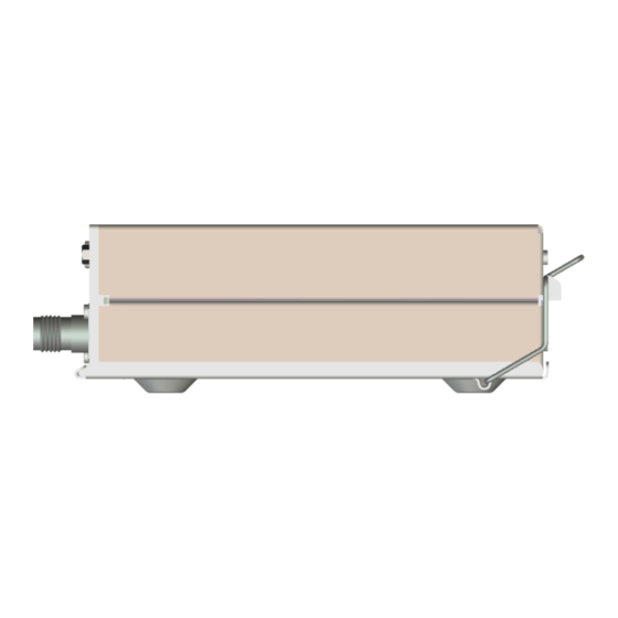
Page 64: Installation Drawings
TT21/TT22 Transponder Installation Manual 22 August 2017 00560-00 13. Installation Drawings 13.1 Mounting tray fixing and overall dimensions All dimensions in millimetres ______________________ Trig Avionics Limited... -
Page 65: Front Panel Controller Dimensions
TT21/TT22 Transponder Installation Manual 22 August 2017 00560-00 Issue AP 13.2 Front Panel Controller Dimensions Controller shown without the mounting adapters (00678-00) used for 57mm (2¼ inch) instrument mounting. All dimensions in millimetres. ______________________ Trig Avionics Limited... -
Page 66: Front Panel Cut-Out Options
TT21/TT22 Transponder Installation Manual 22 August 2017 00560-00 13.3 Front Panel Cut-out Options The front panel controller can be fitted to either the compact mounting hole or a conventional 57mm (2¼ inch) instrument cut-out. The compact mounting is a truncated 58 mm opening; please note that the mounting screws are NOT in the same location for the two options. - Page 67 TT21/TT22 Transponder Installation Manual 22 August 2017 00560-00 Issue AP Note: The following diagram is intended to be to scale, however variations in the printing process mean that you MUST check all dimensions before using it as a template. All dimensions in millimetres.
-
Page 68: Basic Interconnect Diagram
TT21/TT22 Transponder Installation Manual 22 August 2017 00560-00 Issue AP 14. Basic Interconnect Diagram ______________________ Page 60 Trig Avionics Limited... - Page 69 This page intentionally left blank Trig Avionics Limited...
Need help?
Do you have a question about the TT21 and is the answer not in the manual?
Questions and answers