
Related Manuals for World Chemical YD-25NSF


Summary of Contents for World Chemical YD-25NSF
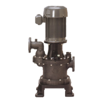
- Page 1 SEALLESS & VALVELESS SELF-PRIMING PUMP SELFREE NON-METALLIC CARBON FIBER REINFORCED POLYPROPYLENE INSTRUCTION MANUAL Version: WCA.0202 YD-25NSF YD-40NSF YD-50NSF...
-
Page 2: Table Of Contents
PREFACE Thank you very much for purchasing World Chemical’s sealless and valveless self- priming pump, SELFREE. The pump is ideal for environments where general specification chemical liquids of ordinary temperatures are used (i.e. non-electrolytic plating). The standard model is a maintenance free pump that has no mechanical seal or bearing. -
Page 3: Safety Precaution
SAFETY PRECAUTION The following procedures are intended to protect you from personal injury and/or property damage. The following symbols classify the degree of danger and explain the damages that could occur when its contents are ignored and the pump is used erroneously. Warning: Non-compliance can lead to fatal or serious injury. - Page 4 SAFETY PRECAUTION (continued) Do not damage, modify or stretch the power cord. Heating or placing heavy objects on the cord will damage it, causing fire and/or electric shock. The pump must be grounded. There is a risk of electric shock if the ground wire is not properly attached. The ground wire must be attached.
-
Page 5: Handling Upon Receipt
HANDLING UPON RECEIPT Inspect the following before use: Make certain the product is what you have ordered. Make sure the model type, discharge output, pump height and voltage specified on the nameplate are as ordered. Check for any damaged or missing parts. Visually inspect or hand-check the unit for any accidental damage or bolts that may have loosened during shipment. -
Page 6: The Principle Of Self-Priming
FEATURES (continued) Valveless This patented VALVELESS feature has been a World Chemical trademark since 1971. Because of this unique priming mechanism, this pump does not require any foot valves. Also, the built-in check valve reduces backflow velocity to retain maximum liquid in the priming chamber at pump shutdown. -
Page 7: Examples Of Use
EXAMPLES OF USE Transferring/circulating high temperature plating liquid to a filtering tank Pumping, transport from a drainage tank or a chemical tank WARNING THIS USE NOT APPLICABLE. -
Page 8: Specification And Performance Curves
SPECIFICATION AND PERFORMANCE CURVES... -
Page 9: Dimensional And Parts Drawing
DIMENSIONAL AND PARTS DRAWING Note: Marked (*) dimension varies depending on the motor size. - Page 10 DIMENSIONAL AND PARTS DRAWING (continued) Discharge Elbow Nut for Stud Bolt Motor Bolts and Washers Hex. Cap screws Priming Plug O-ring Pump Shaft Packing Stud Bolt Oil Seal Upper Flange O-ring Hex. Bolts Dry Seal Motor Bracket Hex. Bolts Cleaning Impeller Plug Pump Body...
- Page 11 DIMENSIONAL AND PARTS DRAWING (continued) PARTS NAME MATERIAL Motor bracket Diallyl Phathalate + FC Motor shaft Shaft slit collar SCS40 Priming plug CFRPP Pump body CFRPP Cleaning plug CFRPP O-ring Impeller locking sleeves Impeller with sleeve CFRPP Drain plug CFRPP Packing for drain &...
-
Page 12: Precautions In Handling The Selfree
PRECAUTIONS IN HANDLING THE SELFREE Remove the blind seals on the outlet and inlet of the pump before attaching pipes to them. Do not rotate the motor in the reverse direction. (Except for an instantaneous reverse rotation to check the rotational direction.) The pump has a patented structure to retain a certain amount of liquid in the casing when the pump is stopped. -
Page 13: Installation And Piping
(d). Approx. 3.3 ft. (1 m) 3.Limit of suction height (for clear water at room temperature). YD-25NSF 8.2 ft. (2.5 m) YD-40NSF 9.8 ft. (3.0 m) YD-50NSF 11.5 ft. (3.5 m) 3.The limit of the suction height (self-priming... -
Page 14: Order Of Assembly
ORDER OF ASSEMBLY Overview Motor Assembly Pump Body Assembly Installation of the joint shaft to the Installation of the o-rings to the motor pump flange Installation of the motor bracket to Installation of the flange to the pump the motor body Installation of the shaft locking Installation of the discharge elbow to... - Page 15 ORDER OF ASSEMBLY (continued) Motor Assembly:Installation of the joint shaft to the motor As the pictures shown below, install the joint shaft to the motor and check the shaft run out the dial gauge. 1. Install the joint shaft to the 2.
- Page 16 ORDER OF ASSEMBLY (continued) Motor Assembly:Installation of the shaft locking sleeve to the motor Install the shaft locking sleeves (2 pcs.) on the motor shaft with screw bolts. Do not tighten them at this time. Rubber The rubber portion must be turned.
- Page 17 ORDER OF ASSEMBLY (continued) Pump Body Assembly:Installation of the pump upper flange to the pump body The pump body is put on the pump upper flange with o-rings. Weight the pump body for a certain installation. When the pump upper flange is installed on the pump body, please be careful about the direction of each part. Pump upper flange Pump body Pump Body Assembly:Installation of the discharge elbow to the pump body...
- Page 18 ORDER OF ASSEMBLY (continued) Pump Body Assembly: Installation of the motor assembly to the pump body Place the pump body onto the motor assembly as a picture shown below. Tighten the pump body and the motor assembly firmly with hex bolts and nuts. Bolt with washer and nut with spring washer and washer.
- Page 19 ORDER OF ASSEMBLY (continued) The impeller gap adjustment Insert the spacer washer on a step of the motor shaft. Install the impeller with the dry seal to the pump Rotate the impeller until a hole Measure a distance of from Measure a distance of in the motor shaft appears, the top of the impeller to the...
- Page 20 ORDER OF ASSEMBLY (continued) Pump Body Assembly: Installation of o-rings to the pump body and the casing 1. Place five o-rings onto the o- 2. Place an o-ring onto the o-ring ring grooves around the bolt holes. groove on the casing. Pump Body Assembly: Installation of the pump casing to the pump body 1.
-
Page 21: Order Of Disassembly
ORDER OF ASSEMBLY (continued) Pump Body Assembly: Installation of the pump base, the drain cap and the priming plug to the pump 1. Place the pump base on the 2. Install the drain cap with a 3. Install the priming plug with pump and fasten them with hex packing to the pump casing. -
Page 22: Troubleshooting
TROUBLESHOOTING Unable to start. Try to rotate the impeller manually. Light. Heavy. Operating condition not Defective electrical Disassembly and inspection. ready. system. Rotate only the motor Rotate only the pump Check the protective Check the panel and manually. manually. device condition. power supply. - Page 23 No pumping can be done, insufficient water volume, insufficient pressure. Check the direction of rotation and motor r.p.m. Reverse rotation. Forward rotation. Rewire two phases of Abnormally slow motor the three phase. r.p.m. Go to Unable to start. Normal motor r.p.m. Can prime.
- Page 24 Vibration and noise. Forward Rotation. Reverse Rotation. Check the shaft center deflection. Rewire two phases of the three phase. Improper. Proper. Improper installation. Check the vibration or noise source. Inside the pump. Motor Bearing. Piping and valve Foundation section. section. Worn or damaged Low suction pressure due Water hammer.
-
Page 25: Warranty Period And Coverage
WARRANTY PERIOD AND COVERAGE The warranty period is one year from the date of delivery. During the warranty period, if the unit fails or becomes damaged in a normal operating condition due to manufacturing defect(s), the failure or damaged part(s) will be repaired free of charge. There will be a service charge for repairing the following failure(s) or damage(s) and for the replacement of worn part(s): Any failure or damage occurring after the warranty period. - Page 26 When requesting repair service, please provide us with the following information: Model name and serial number How long the unit has been used and its condition Damaged section and its condition Liquid pumped (name of liquid, specific gravity, liquid temperature, presence of slurry) When returning a failed pump, please ensure to thoroughly wash the inside of the pump to prevent the danger of liquid leakage from the pump during transit.
-
Page 27: Contact Information
CONTACT INFORMATION North / South America 20610 Manhattan Place, #116 Torrance, CA 90503 U.S.A. TEL: 310-328-9114 · FAX: 310-328-9441 TOLL FREE E-mail: wcusa@worldchemicalusa.com 1-888-860-3364 Website: http://www.worldchemicalusa.com Asia / Europe Tousen Higashi Azabu Bldg., 7 Floor, 1-5-2, Higashi Azabu, Minato-ku, Tokyo 106-0044 Japan TEL: 03-3588-1140 ·...
Need help?
Do you have a question about the YD-25NSF and is the answer not in the manual?
Questions and answers