Table of Contents
Advertisement
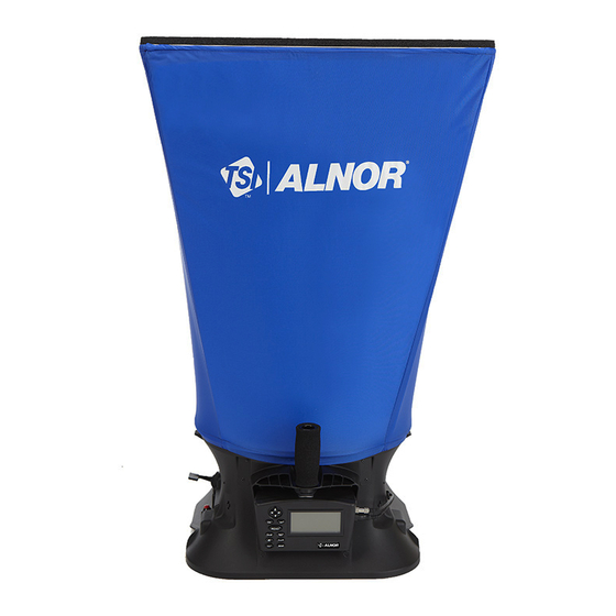
ALNOR
ELECTRONIC
®
BALANCING TOOL
MODELS EBT730/EBT731
OWNER'S MANUAL
P/N 6005725, REV D
OCTOBER 2014
®
Model EBT731 Balometer
Model EBT730 Micromanometer
Air Balancing Instrument
(shown with standard and optional accessories)
GlobalTestSupply
www.
.com
Find Quality Products Online at:
sales@GlobalTestSupply.com
Advertisement
Table of Contents


Need help?
Do you have a question about the EBT730 and is the answer not in the manual?
Questions and answers