Table of Contents
Advertisement
Quick Links
Advertisement
Table of Contents
Troubleshooting

Related Manuals for Alnor AXD 530


Summary of Contents for Alnor AXD 530
- Page 1 OWNER’S MANUAL AXD 530 MicroManometer ® T S I ® C o m p a n y...
-
Page 2: Table Of Contents
Table of Contents Features Using the AXD530 Safely Getting Started Installing Batteries Preparing the Instrument Attaching the Optional Pitot-Static Probe Start-Up Sequence Zeroing the Instrument The Display Modes AXD530 Keypad The AXD530 Keypad Key Functions Using the AXD530 Basic Functions To Change Units Measurement Modes Pressure Selection... -
Page 3: Features
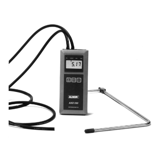
Features The AXD530 MicroManometer is a meter that measures differential pressure. It is also capable of measuring and displaying air velocity. Functions are selected through a 3-key pad. The AXD530 displays measurement results on a liquid-crystal display (LCD), with additional dis- play segments for units of measure and low battery indication. -
Page 4: Using The Axd530 Safely
Using the AXD530 Safely • When using the instrument to check air WA R N I N G flow in an elevated workplace, make certain that you can safely raise and hold the instrument while making mea- surements. This is especially important when you are working on a ladder. -
Page 5: Getting Started
Getting Started Installing Batteries The AXD530 uses three (3) AA size non-recharge- able batteries. The unit was shipped with batteries not installed. You will find the batteries in the in- strument package. To install the batteries: • Loosen the battery cover screw on the rear of the instrument. -
Page 6: Start-Up Sequence
Before you begin taking measurements, the AXD530 must be zeroed by following these steps: • Most hand-held meters using differen- tial pressure sensors require a warm-up time. Turn on your Alnor AXD530 a minimum of 5 minutes before zeroing and taking your first measurements. - Page 7 • Make sure there is no air flow past a Pitot-static probe (also verify that none of the tubing is pressurized by acciden- tal squeezing). • Press the ZERO key until [ appears on the display. The instrument will automatically zero its readings. Repeat this procedure if necessary, because at high resolutions the AXD530 will read small pressure changes.
-
Page 8: The Display
The Display The AXD530 uses a 4-digit, 7-segment LCD. As a result, measurements exceeding 9,999 of a given unit of measure will be displayed in a scientific notation format of XXEY. The actual reading will be rounded to the nearest thousand, XX. The Y indicates the number of zeros after XX. -
Page 9: Axd530 Keypad
AXD530 Keypad The AXD530 Keypad The internal clock rate of the AXD530 software may cause the meter to react slowly to a key push. The reaction time of a key push will vary with different functions (1–3 seconds). Maintain pressure on the desired key until you see the required response on the display. -
Page 10: Using The Axd530
Using the AXD530 Basic Functions To Change Units: • Push and hold the UNIT key. • The display annunciator will move to the left of the LCD beginning from the right. • Release the UNIT key at the desired Display with annunciator location. -
Page 11: Velocity Selection
Velocity Selection: Air velocity measurement can be accomplished using a Pitot-static probe. The following equations are used for pressure to velocity conversions: Velocity (fpm) = 4005 √ Pressure where Pressure is in inches H Velocity (m/s) = 1.29 √ Pressure where Pressure is in Pa The velocity calculations assume standard condi- tions. -
Page 12: Maintenance & Troubleshooting
Maintenance & Troubleshooting Maintenance Periodic maintenance should be performed on the meter. • Batteries should be replaced when the low battery indication is on or when the unit turns itself off after power-up. • Batteries should be removed from the meter if it will not be used for two (2) months or longer. -
Page 13: Troubleshooting
Troubleshooting Symptom Check DISPLAY SHOWS [ The measured value is beyond the instrument’s range. Be sure there is no applied pressure, then press ZERO. DISPLAY SHOWS The internal connection between the meter and ] the sensor is faulty. Turn the meter off, then turn it back on again. -
Page 14: Repair Information
Repair Information Contact the distributor in your country, or Alnor Instrument Company directly, before returning your instrument. See INSTRUCTIONS FOR RETURN. Follow the procedure carefully as it will expedite processing. Failure to follow the procedure may cause return of the unit unrepaired. Send your instrument to the factory transportation prepaid. -
Page 15: Instructions For Return
Instructions for Return Damaged in Transit All shipments are carefully examined by Alnor Qual- ity Assurance and carefully packed for shipment. On receipt, if the shipping container appears to have been damaged during shipment, the instrument should be thoroughly inspected. The delivering carrier’s papers should be signed noting the appar-... - Page 16 Please note that instruments received improperly marked or without an accompanying Purchase Order may be returned at your expense. Please also note that if an RMA number has been assigned, it will be canceled if the instrument is not received by ALNOR within 60 days.
-
Page 17: Ownership/Calibration Log
Ownership/Calibration Log Equipment Log Date of Purchase ___________________________________________________ Calibration Record __________________________________________________ 1. __________________ 2. _________________ 3. ___________________ 4. __________________ 5. _________________ 6. ___________________ 7. __________________ 8. _________________ 9. ___________________ 10. __________________ 11. _________________ 12. ___________________ Notes: ____________________________________________________________ _________________________________________________________________ _________________________________________________________________ _________________________________________________________________ _________________________________________________________________ _________________________________________________________________ _________________________________________________________________... - Page 18 Alnor’s liability for this product is limited to the above stated warranty and shall not in any event exceed the cost of the prod- uct. In no event will Alnor be liable for any direct or consequen- tial damages, including but not limited to lost profits, loss of use, inaccuracies, loss of data, dismantling or reinstallation.
Need help?
Do you have a question about the AXD 530 and is the answer not in the manual?
Questions and answers