Table of Contents
Advertisement
Quick Links
Advertisement
Table of Contents

Related Manuals for Alnor AirGard 405


Summary of Contents for Alnor AirGard 405
- Page 1 OWNER’S MANUAL ® Model 405 AirGard Fume Hood Monitor...
- Page 2 Seller Service Policy Knowing that inoperative or defective instruments are as detrimental to Alnor as they are to our customers, our service policy is designed to give prompt attention to any problems. If any malfunction is discovered, please contact your nearest sales office or representative, or call Alnor’s Customer Service department at (800) 424-7427 (USA) and (1) 651-490-2811...
-
Page 3: Table Of Contents
TABLE OF CONTENTS General Description ..............2 Setup....................3 Installation ..................5 General ..................5 Tools Required ................5 Procedure..................6 Calibration..................7 Equipment..................7 Procedure..................7 Step by Step Operation..............9 Alarm Acknowledgment..............9 Alarm Test ...................9 Horn Disable (from keypad)............9 Appendix A: Maintenance & Troubleshooting ..........10 Service Policy................11 Ship To ..................11... -
Page 4: General Description
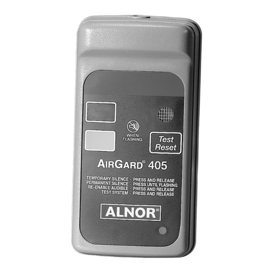
Figure 1: Front view of instrument Note: For proper operation of the instrument, you must install and calibrate the AirGard 405 monitor. The entire manual should be read first before proceeding with the actual installation and calibration of the instrument. -
Page 5: Setup
Setup The AirGard 405 fume hood monitor contains several configuration options. Two connectors provide access to remote control devices and firmware configuration jumpers. Observe the back of the monitor. Locate the two connectors at the left-center of the printed circuit board marked J3 and JP1. - Page 6 Pole 1 of JP1 is used to select the relay configuration. Without the jumper installed, the relay is Normally Closed (NC) during normal airflow and Normally Open (NO) during an alarm condition. Installing a shorting jumper across pole 1 will cause the relay to be Normally Open (NO) during normal airflow and Normally Closed (NC) during an alarm condition.
-
Page 7: Installation
To monitor face velocity, the air Figure 3: Front view of fascia outlet port at the back of the AirGard 405 is connected to the Figure 3: sidewall inside the fume hood as Front view of fascia shown in figure 4. A flexible hose is... -
Page 8: Procedure
Procedure Step 1: Detach the back plate from the monitor. Step 2: Use the back plate (figure 3) as a template to drill two holes, 0.104" diameter, to secure the back plate to the fume hood. Step 3: Use the back plate as a template to drill one hole, 0.75"... -
Page 9: Calibration
Personnel calibrating the AirGard 405 monitor must be completely aware of the regulations and guidelines specific to their application. - Page 10 WARNING This method is only used as a temporary condition to set the low flow point. Make sure airflow is restored to proper level after calibration. Step 5: Using a properly calibrated thermoanemometer, determine the velocity through the face of the hood by taking a detailed velocity traverse.
-
Page 11: Step By Step Operation
Step-By-Step Operation Alarm Acknowledgment The horn and red indicator will turn on approximately six seconds after an alarm condition is detected. To mute the horn, press and release the TEST/RESET button. Note that after an alarm condition has been detected, the red indicator will stay on. The horn will remain muted until airflow is restored to normal levels. -
Page 12: Appendix A: Maintenance & Troubleshooting
APPENDIX A: Maintenance & Troubleshooting Maintenance The outside of the AirGard 405 monitor may be wiped clean with mild soap (dish washing detergent) and water on a damp cloth to remove finger marks, oils or residue. Do not use abrasives or solvents. Do not immerse the monitor or allow liquids to enter the case. -
Page 13: Service Policy
TSI’s Customer Service department at (800) 424-7427 (U.S. and Canada only). Ship to: TSI Incorporated Alnor Products 500 Cardigan Road Shoreview, MN 55126 USA Toll-Free (800) 424-7427 Telephone (651) 490-2811 Fax (651) 490-3824 Email: customerservice@Alnor.com... - Page 15 ® AIRGARD 405 MONITOR SPECIFICATIONS Instrument Dimensions 6.05" high x 3.15" wide x 1.8" deep (15.4 x 8.0 x 4.6 cm) Instrument Weight 8 oz (0.23kg) Shipping Weight 1 lb 8 oz (0.68 kg) Green Indicator 0.75" x 0.5" (1.9 x 1.3 cm) Red Indicator 0.75"...
- Page 16 TSI Incorporated Alnor Products 500 Cardigan Road Shoreview, MN 55126 USA Toll-Free (800) 424-7427 Telephone (651) 490-2811 February 2003 Fax (651) 490-3824 Printed in USA Email: customerservice@Alnor.com Part No. 116-159-093 Rev. 8 www.alnor.com © Copyright 1997–2003 TSI Incorporated...
Need help?
Do you have a question about the AirGard 405 and is the answer not in the manual?
Questions and answers