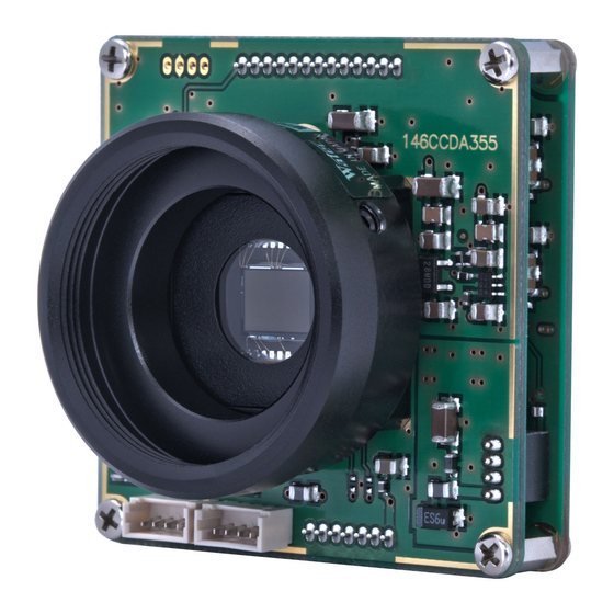
Watec WAT-910BD Communications Manual
Spi digital out, color board camera unit
Hide thumbs
Also See for WAT-910BD:
- Hardware manual (65 pages) ,
- Manual (63 pages) ,
- User manual (30 pages)
Summary of Contents for Watec WAT-910BD
- Page 1 WAT-910BD SPI COMMUNICATION MANUAL(Digital Out) WAT-910BD SPI COMMUNICATION MANUAL(Digital Out) Ver.1.0 Jul.01,2016 Watec Co.,Ltd.
- Page 2 WAT-910BD SPI COMMUNICATION MANUAL(Digital Out) History Ver. No. Date Changes Remark 1.00 2016.07.01 First edition - i -...
-
Page 3: Table Of Contents
WAT-910BD SPI COMMUNICATION MANUAL(Digital Out) Contents ........1 1. INTRODUCTION ........1 2. LEGAL DISCLAIMER ........1 3. OVERVIEW ........2 4. SPI COMMUNICATION ........4 5. DEGITAL OUTPUT FUNCTION SETTING ........4 5.1 DIGITAL OUTPUT ON/OFF ........5 5.2 DETAIL SETTINGS ........ -
Page 4: Introduction
WAT-910BD. Please refer to Chapter 6 of "WAT-910BD H / W manual" to know that how to use the SPI communication function. About the video format of the digital output, please refer to Chapter 5 of "WAT-910BD H / W Manual". -
Page 5: Spi Communication
WAT-910BD SPI COMMUNICATION MANUAL(Digital Out) 4.SPI COMMUNICATION In order to operate the related parameters of the digital output function, use the following commands. 1) CAMERA PARAMETER READ SPI Write "data set" (send to camera MCU), Address:0x082 Symbol Value Checksum (CS) specifies the lower 1 byte of the calculated value (C1 + C2 + ADR + DAT). -
Page 6: Camera Parameter
WAT-910BD SPI COMMUNICATION MANUAL(Digital Out) 2) CAMERA PARAMETER WRITE SPI Write "data set" (send to camera MCU), Address:0x082 Symbol Value *1: Parameter Value. *2: Checksum (CS) specifies the lower 1 byte of the calculated value (C1 + C2 + ADR + DAT). -
Page 7: Degital Output Function Setting
WAT-910BD SPI COMMUNICATION MANUAL(Digital Out) 5. DEGITAL OUTPUT FUNCTION SETTING 5.1 DIGITAL OUTPUT ON/OFF Camera Parameter Address DIGIT OUT 0x5E2 - - - - - - - 0:OFF 1:ON *Factory setting value: 0x00 By using DIGIT OUT(0x5E2:Bit0), the digital output will be turned ON/OFF. -
Page 8: Detail Settings
WAT-910BD SPI COMMUNICATION MANUAL(Digital Out) 5.2 DETAIL SETTINGS 5.2.1 CLOCK PHASE (CLK PHASE) By using the bit-3, the phase of digital output clock signal DCK (connector: J6, pin number: 4) is inverted. Camera Parameter Address DIGIT OUT DYC RANGE COLOR ID... -
Page 9: Color Id (Color Id)
By using Bit-4, the output order of the chroma signal(Cb,Cr) and the luminance signal(Y) is changed. By using Bit-5, the output order of the chroma signal(Cb) and the chroma signal(Cr) is changed. (Since WAT-910BD is a B/W camera, bit-5 is invalid for substantially, and the data values of Cb and Cr are all 0x80.) The factory setting value is (bit-5, bit-4) = (0,0), it means that the digital data order are (Cb, Y, Cr, Y). -
Page 10: Output Data Range (Dyc Range)
WAT-910BD SPI COMMUNICATION MANUAL(Digital Out) 5.2.3 OUTPUT DATA RANGE (DYC RANGE) By using the bit-6, the data output range of the digital output signal bit 7 to 0 (connector: J6, pin number: 6-12) are changed. Camera Parameter Address DIGIT OUT... -
Page 11: Digital Output On/Off (Digit Out)
WAT-910BD SPI COMMUNICATION MANUAL(Digital Out) 5.2.4 DIGITAL OUTPUT ON/OFF (DIGIT OUT) By using DIGIT OUT, the digital output will be turned ON/OFF.(It is same function as address 0x5E2 Bit-0.) Camera Parameter Address DIGIT OUT DYC RANGE COLOR ID CLK PHASE...


Need help?
Do you have a question about the WAT-910BD and is the answer not in the manual?
Questions and answers