
Related Manuals for Velleman AER Domus


Summary of Contents for Velleman AER Domus
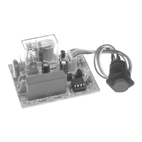
- Page 1 Total solder points: 202 Difficulty level: beginner 1 advanced POWER SAVER / TIMER K8075 ILLUSTRATED ASSEMBLY MANUAL H8075IP-1...
-
Page 3: Specifications
Assembly hints The power saver turns off your equipment after a preset time. It helps you save money and it increases safety. FEATURES: Single button operation with LED mode indicator continuous : 24h turn-off timer slow flashing : 4h or 8h turn-off timer fast flashing : 1h or 2h turn-off timer : idle Choose short or long-running timers (one-time jumper setting) - Page 4 Assembly hints 1. Assembly (Skipping this can lead to troubles ! ) Ok, so we have your attention. These hints will help you to make this project successful. Read them carefully. 1.1 Make sure you have the right tools: • A good quality soldering iron (25-40W) with a small tip.
- Page 5 3- Trim excess leads as close as possible to the solder joint REMOVE THEM FROM THE TAPE ONE AT A TIME ! AXIAL COMPONENTS ARE TAPED IN THE CORRECT MOUNTING SEQUENCE ! You will find the color code for the resistances on our website: http://www.velleman.be/common/service.aspx...
- Page 6 Construction 1. Diodes. Watch the polarity ! 4. Metal film resistors (1%) 6. IC socket. Watch the position of the notch! D1 : 1N4148 IC1 : 8p R... D... CATHODE : 330K (3 - 3 - 4 - B - 9) : 330K (3 - 3 - 4 - B - 9) 2.
- Page 7 Construction 8. Transistors 11. Shunt 13. VDR T1 : BC547B T2 : BC547B 9. Board to wire connector Choose timer : VDR1 : VDR300 SK6 : 4p Mounted : 2h / 8h Not mounted : 1h / 4h 14. Electrolytic capacitors Watch the polarity! 12.
- Page 8 Construction 15. Capacitor 17. IC. Watch the position of the notch! IC1 : VK8075 (programmed PIC10F200-I/PG) Choose operation voltage : 230V : C5 : 0,47µF / 630V 115V : C5 : 0,68µF / 400V CHECK THOROUGHLY ALL THE COMPONENTS FOR MISS 16.
- Page 9 Wiring the push button 18. Wiring the push button Cut off a piece of shrinkable tube with a lenght equal to 2,5cm. Fig. 2.0 Slide the shrinkable tube over the wires of the female 'board to wire'-connector (fig. 2.0) Solder the 4-pole female 'board to wire' connector to the push button using the figure below to check the accuracy of the connections (see figure 3.0) Attention: Always make sure to slide down the shrinking tube far enough from the soldering points! (Brown)
- Page 10 Wiring the push button In case you want to use a different push button, make sure it is rated for the AC-voltage. If you do not use the included push button, you can mount a 3mm LED on the PCB. COLOR= 2...5 LD...
- Page 11 Final connection & use 19. Final connection & use CAUTION: All PARTS OF THE CIRCUIT CARRY DANGEROUS VOLTAGES (MAINS) ! OBSERVE ALL SAFETY REQUIREMENTS Push button THAT MIGHT APPLY ! AC POWER MOUNT THIS KIT PREFERABLY IN AN ISOLATED ENCLOSURE Connect your application (ex.
- Page 12 Never modify the JP1 mode setting while the unit is still live! Jumper selection: First, choose the desired timer function, i.e. a long-term or a short-term timer. (1) Long-term timer. Mount the jumper (JP1) At power-on, the pushbutton LED (or LD1) will flash slowly twice, hereby indicating that long-term timers have been selected (2h or 8h turn-off timer).
- Page 13 Use : Push button briefly: turn-on relay and toggle between a short or a long turn-off delay. Short turn-off delay (1h or 4h, depending on setting of jumper JP1) Pushbutton LED (or LD1) blinks fast. Long turn-off delay (2h or 8h, depending on setting of jumper JP2) Pushbutton LED (or LD1) blinks slowly.
- Page 14 Diagram 20. Schematic diagram...
- Page 15 21. PCB...
- Page 16 VELLEMAN Components NV Legen Heirweg 33 9890 Gavere Belgium Europe www.velleman.be www.velleman-kit.com Modifications and typographical errors reserved © Velleman Components nv. H8075IP - 2005 - ED1 5 4 1 0 3 2 9 3 4 8 3 3 5...
Need help?
Do you have a question about the AER Domus and is the answer not in the manual?
Questions and answers