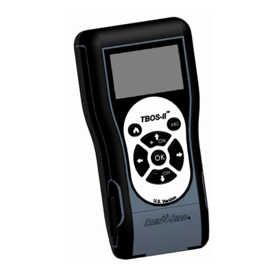
Rain Bird TBOS-II Manual
Field transmitter
infra red and radio communication
868 mhz (eu, south africa)
915 mhz (usa, canada, mexico, australia)
Hide thumbs
Also See for TBOS-II:
- Manual (44 pages) ,
- User manual (21 pages) ,
- Quick reference manual (9 pages)

Related Manuals for Rain Bird TBOS-II


Summary of Contents for Rain Bird TBOS-II
- Page 1 TBOS‐II™ Field Transmitter Infra Red and Radio Communication 868 MHz (EU, South Africa) 915 MHz (USA, Canada, Mexico, Australia) ENGLISH DRAFT – FIELD TEST VERSION July 2011 ...
- Page 2 l'intention des autres utilisateurs, il faut choisir le type STATEMENT d'antenne et son gain de sorte que la puissance isotrope rayonnée équivalente (p.i.r.e.) ne dépasse pas l'intensité RF EXPOSURE nécessaire à l'établissement d'une communication This device complies with FCC RF and Industry Canada satisfaisante. ...
-
Page 3: Table Of Contents
Summary A. System TBOS‐II Introduction ...................... 5 1. The TBOS‐II System ........................ 5 2. System Description ........................ 6 TM 3. New features of TBOS‐II System .................... 6 TM 4. TBOS‐II Field Transmitter Introduction .................. 7 B. Field Transmitter Start‐up / Configuration .................. 9 1. First Use ............................ 9 2. Field Transmitter Configuration de la console (Settings Menu) .......... 9 Setting Time/Date ........................... 9 Adjusting the contrast ........................ 10 Customize the field transmitter name (16 letters and digits) ............ 10 Field Transmitter language selection .................... 11 Setting the screen lighting time .................... 11 Restore initial settings ........................ 11 Displaying field transmitter data .................... 11 ... - Page 4 2. State switch of a Rain Sensor .................... 25 3. State switch of a flow sensor ..................... 25 Leakage ............................ 25 Excessive Consomption (SEEF) ...................... 26 FloWatch ............................ 26 G. TBOS Radio Network Building ....................... 26 1. Radio range increase between Field Transmitter and Radio Adaptor TBOS‐II™ ...... 26 Optimum Radio range between Transmitter and Radio Adaptor .......... 26 TBOS Radio Relays ......................... 27 2. TBOS Centralization on IQ V2 Softawre .................. 27 IQ‐TBOS Master Radio Module ..................... 27 IQ Software ............................ 28 3. TBOS‐II™ Field Transmitter‐Radio Relay Communication ............ 28 TBOS‐II Field Transmitter to communicate with radio relay ............ 28 Relay radio marking ........................ 29 Network number Modification of Radio Devices ................ 29 4. Automatic Radio finding for TBOS Radio Relays ............... 30 Automatic Radio relay finding with the Field Transmitter ............ 30 ...
-
Page 5: A. System Tbos-Ii Tm Introduction
Preamble RAIN BIRD thanks you for having purchased a TBOS‐II™ series field transmitter. This new transmitter is universal and is compatible with the entire TBOS™ range (old and new generation). Adding a TBOS‐II™ Radio Adaptor enhances the programming of the old generation TBOS™ modules. Once the program data has been entered into the field transmitter, it could be sent into the Control Modules in one of two ways: • • Via an infrared connection, using the Via a radio connection, using the cord supplied with the transmitter. TBOS‐II™ Radio Adaptor plugged onto the Control Module. The new Field Transmitter also includes new features that will provide additional benefits for the management of your TBOS™ and/or TBOS‐II™ Control Modules. * except VRM1 and FS1. The information contained in this document is purely indicative. It may be changed without notice and does not represent a commitment on the part of RAIN BIRD. A. System TBOSII Introduction 1. The TBOSII System The new generation system works with products using the 868MHz (EU, South Africa) or 915 MHz (US, Canada, Mexico, Australia) free frequency band. System composition : • A universal FIELD • One (or more) • A TBOS‐II™ RADIO TRANSMITTER (FT) to TBOS™/TBOS‐II™ CONTROL ... -
Page 6: System Description
2. System Description Old TBOS System TM TM Old TBOS Control Module OTBOS Radio Adaptor Old TBOS Field Transmitter Nouveau Système TBOS‐II TM TM New TBOS‐II Field Transmitter New TBOS‐II Control Module TBOS or TBOS‐II Control ... -
Page 7: Tbos-Ii
TM • Customizable name for the TBOS II Control Module • Customizable name for the station 4. TBOSII Field Transmitter Introduction TM Backlit dot • Dimension : 160*70*30 (mm) Radio Antenna matrix • Dark grey ABS housing • Waterproof 7‐key keypad • UV‐resistant plastic • Operating temperature: ‐10° and +65° C* • Allowable air humidity : 95% max (de 7‐key keypad 2 AAA rechargeable 4°C to 49°C) NiMH batteries (on • Storage temperature: ‐ 40°C to + 66°C the back) • Removable infrared cord • Backlit monochrome LCD display (128 x 64 pixel) ... - Page 8 The infra red cord is removable. If you do not need it, remove it and replace it by the provided plug by following the steps below: Unscrew the infra red cord Unscrew the field transmitter back security. plane. Pull up the cord… … and unplug it. Place the provided plug in the free Scew again the security device space to insure sealing of the field before closing the field transmitter. transmitter. 8 ...
-
Page 9: Field Transmitter Start-Up / Configuration
B. Field Transmitter Startup / Configuration 1. First Use When equipped with TBOS‐II Radio Adaptor, the old TBOS Control Module is featured with new features. Before operation, the Field Transmitter must be charged for 10 hours at least before its first use. Batteries replacement: The battery life depends on the daily use of the field transmitter and the backlight on time setting. If you have to change the batteries, use batteries with same caracteristics (GP NiMH Battery – GPHCH73 N04 2,4V, 750 mAh). WARNING : To access to programming screens, the field transmitter has to be set and connected to a TBOS /TBOS‐II Control Module via radio or infra red. To wake‐up the field transmitter, press Home during 2 seconds. Once the field transmitter is charged, make the initial settings: 2. Field Transmitter Configuration de la console (Settings Menu) Proceed to the first setting adjustments : ‐ Date and time settings, ‐ Contrast adjustment, ‐ Setting the name of the field transmitter, ‐ Language selection, ‐ Screen lighting time adjustment, ‐ Defaults setting Restoration, ... -
Page 10: Adjusting The Contrast
‐ Changing the time: o Select "Time" + press OK o Move from hours to minutes by pressing o Increase or decrease the hours or minutes using the ON & OFF keys and confirm by pressing OK ‐ Changing Time Format : o Select « Time Format » + press OK o Select 12 or 24 hours ‐ Changing the date: o Select "Date" + press OK o Move from Day to Month to Year by pressing arrows o Increase or decrease each value using the ON OFF keys and confirm by pressing OK ‐ Changing date format o Select « Date Format » + press OK o Select Mont/Day/year or Day/month/year Adjusting the contrast ‐ Select "Contrast", from the "Settings" menu and confirm by pressing OK ‐ Set the contrast level using the ON OFF keys and confirm by pressing OK ... -
Page 11: Field Transmitter Language Selection
The "Space" character is situated after the letter "Z" Field Transmitter language selection ‐ Select "Languages" in the "Settings" screen and confirm by pressing OK ‐ Then chose the desired language using the ON & OFF keys, and confirm by pressing OK Proposed languages: French, English, Spanish, Italian, Germany, Portuguese, Greek and Turkish. Setting the screen lighting time ‐ Select "Lighting time‐out" from the "Settings" screen and confirm by pressing OK ‐ Set the length of time using the ON OFF keys and confirm by pressing OK Restore initial settings ‐ Select “Settings“, select “Restore Settings“and valid by pressing OK. ‐ Confirm by OK Displaying field transmitter data ‐ Select "About" from the "Settings" screen and confirm by pressing OK ‐ The following information will then appear on the screen: o Field transmitter ID o The embedded software version 11 ... -
Page 12: Using The Field Transmitter Via Infra Red Connection (Ir)
C. Using the Field Transmitter via Infra Red Connection (IR) The field transmitter is able to communicate via infrared with all types of old or new generation TBOS™ control modules. Certain exclusive functions are only accessible when the field transmitter is connected to a TBOS‐II™ IR control module, i.e.: ‐ Water budget, ‐ Assignment of a station to several programs, each with a different time, ‐ Station test, ‐ 1 to 31 day cyclical irrigation schedules (1 to 6 days for the TBOS model), ‐ Customisation of TBOS‐II module and its stations names, ‐ Saving of program in the control module The field transmitter can also add the "Rain Delay" function to all TBOS™ control modules. It has 6 memory storage areas that can store 6 different programs: 3 are dedicated to old model TBOS™ modules and the 3 others to the TBOS‐II™ modules. It also allows to cancel all or individual programs contained in any TBOS™ module (TBOS™ module reset). 1. Programming TBOSII Field Transmitter TM Before programming process, you MUST connect the field transmitter infra red cord on the TBOS /TBOS‐II Control Module Infra red connector. ‐ To wake‐up the Field Transmitter, press Home during 2 sec. ‐ Press the OK key, select "TBOS IR infrared" with and confirm by pressing OK in order to read the program data contained in your TBOS™ Control Module. The reading of program data can take between 2 and 12 seconds according to the TBOS™ module version (old or ... -
Page 13: Start Times
Then, select "Programs" in the Infrared welcome screen, and confirm by pressing OK ‐ Select "Watering days" and confirm by pressing OK. You can then choose a specific watering cycle: o Week (custom cycle) – All days set to ON by default o Even‐numbered days o Odd‐numbered days o Odd numbered days 31 (watering performed on odd days except the 31) o Cyclical (every " X" days) ‐ If you select "Custom cycle" (all days set to ON by default) o Select the desired program A, B or C in the flashing box in the top left‐hand corner of the screen using the ABC key o Using the ON & OFF keys, select the watering days in the calendar per program and confirm by pressing OK ‐ If you choose "Cyclical" o Select the watering cycle (1 to 6 days for the TBOS™ / 1 to 31 days for the TBOS‐II™ controller only) using the ON OFF keys, and confirm by pressing OK o Then, enter your watering cycle start date "dd/m/year" using the ON OFF keys Start times ‐ Select "Start times" and confirm by pressing OK. ‐... -
Page 14: Watering Run Time
When you exit this screen, the watering starts will automatically be sorted in chronological order. Watering run Time Each station can be assigned to the 3 programs A, B and C, with different times for each program (TBOS‐II™ controllers only). ‐ Then select "Programs" from the Infrared welcome menu and confirm by pressing OK ‐ Select "Valve run time" and confirm by pressing OK. ‐ Select the program A/B or C to be assigned to each valve (1 to 6) using the ON OFF keys, then go to hours and minutes by pressing arrows. Confirm by pressing OK Transmitting time, date and program ‐ Press the centre key of the field transmitter to return to the Infrared welcome screen. ‐ Select "Transmit" and confirm by pressing OK WARNING: If you wish to synchronize time and date of the TBOS™ controller with the field transmitter, simply read the contents of the TBOS™ module and make a transmission without altering the program. 1. Water Budget Programming You have the option of changing the watering time for each one of the 3 programs A, B and C and for each month. Seasonal adjustment per program ‐ Select "Water budget" and confirm by pressing OK ‐ Then select "per program" and confirm by pressing OK ‐ Then choose to which of the programs A, B or C to assign the water budget. Modify the permitted watering run times in 1% increments (from 0 to 300%) and confirm by pressing OK 14 ... -
Page 15: Seasonal Adjustment Per Month
By default: 100% = no change to watering run times > 100% = increase of watering run times < 100% = decrease of watering run times. Seasonal adjustment per month ‐ Select "per month" and confirm by pressing OK ‐ Change the watering run times for each of the months by fractions and confirm by pressing OK. Programs A, B and C will be affected. WARNING : Water budgets per program and per month are cumulative. Example of water budget: ‐ A valve programmed with a time of 10 minutes on program A and 20 minutes on program B. ‐ A water budget set at 50% on program. A and 200% on program B. ‐ Un water budget set at 300% for the current month => The effective watering run time will be 15 min (10 x 50% x 300% = 15) on program A and 120 min (20 x 200% x 300% = 120) on program B The water budget does not apply to manual actions. The maximum watering run time is 24 hours. 2. Cancel irrigation programs ‐ Select "Clear programs" from the TBOS™ IR welcome menu and confirm by pressing OK ‐ Then select the type of program to delete: o Individual program to delete only one of the programs (A, B or C) o All programs (A, B and C) o Reset factory parameters (TBOS name = ID, station names, Rain Delay, programs A B C empty, etc.) ‐... -
Page 16: Reading Irrigation Programs
3. Reading Irrigation Programs ‐ Select "Check programs" from the Welcome screen and confirm by pressing OK ‐ Then select the desired display and confirm by pressing OK: o Review programs that displays details of each of the programs A, B and C + Rain Delay + Water budget per month. o Program run times (programs A, B and C) o Station run times (1 to 6) 5. Transmitting an irrigation program to TBOS™/TBOSII™ Control Module Once programs A, B and C have been set, they can be sent via infrared to the connected TBOS/TBOS‐ II™ Control Module. ‐ Select "Transmit" from the Welcome menu and confirm by pressing OK ‐ The program to be downloaded will be displayed on the screen. Confirm the transmission by pressing OK (If the program is uncompleted, an alert may be displayed) D. Manual actions Manual actions override other actions. Any running program will therefore be deactivated to take account of the manual function. 1. Cancel Irrigation ‐ Select "Manual watering" in the TBOS™ IR welcome screen and confirm by pressing OK 16 ... -
Page 17: Manual Station Launch
‐ Then, select the type of manual action to be performed: o Stop watering o Start a station o Start a program A, B or C o Perform a test on all stations. ‐ Select the "Stop watering" menu and confirm by pressing OK to manually stop the watering operating in progress. 6. Manual Station launch ‐ Select "Start station" and choose the station to be started with ON/OFF and confirm by pressing OK ‐ Then, set the manual watering run time and confirm by pressing OK Watering will start after a 2 second delay. WARNING : ‐ The old TBOS Control Modules start manually a station for the run time set‐up in its program. For a manual station launch, the associated valve MUST have a run time set‐up. ‐ With TBOS‐II Control Modules, the duration of a manual station run is customizable. 7. Manual Program Launch ‐ Select "Start program" and choose one of the 3 programs A, B or C to be started using the ON OFF keys and confirm by pressing OK. ... -
Page 18: On/Off & Rain Delay
‐ Then, set the watering test run time (1 to 10 min) using the ON OFF keys, and confirm by pressing OK to transmit the program data to the control module. 9. ON/OFF & Rain Delay The TBOS‐II universal filed transmitter has an "OFF" function that allows you to disable watering (e.g. when it rains) regardless of programming. To re‐enable watering, the default position is "ON". ‐ Select "ON/OFF" from the Welcome menu and confirm by pressing OK ‐ Then, select the time during which you wish to stop the program (1 to 14 days or complete shut‐down) and confirm by pressing OK The data will then be immediately transmitted to the TBOS™ and is totally independent of the programming. If you select the "OFF" option, watering will be automatically stopped until switched back on. To restart, perform the same steps as above and select the "ON" option. General Program Saving in TBOSII™ Field Transmitter The new TBOS‐II™ universal field transmitter contains an internal memory that can store up to 3 different programs (irrigation + names). You can, for example, create 3 different programs covering specific seasons (Spring/ Summer/ Autumn) and save them in the field transmitter. This action allows you to save time, as they can be transmitted by a simple click to other TBO/TBOS‐II™ Control Modules. ‐ Select "Program templates" from the TBOS™ IR welcome screen and confirm by pressing OK ‐ Then, choose between two options: "Save" the data in the field transmitter or "Restore" the data. The "Restore" function allows you to delete all data contained in the field transmitter except for the time and the date. "Restore" replaces the program displayed on the field transmitter. A transmission must then be made to the control module. Saving program into the TBOSII™ Control Module ... -
Page 19: Customization Of Control Module(S) And Station(S) Names
‐ Select " TBOS Backup " from the TBOS™ welcome menu and confirm by pressing OK. The console can send a save instruction to the TBOS™, which will then make a copy of its current program in its backup memory. ‐ Then choose "Save" if you wish to save your program in the internal memory of the control module. Confirm by pressing OK ‐ Choose "Manual recall". Upon receiving this instruction, the TBOS™ immediately replaces its current program with the backup program. ‐ Choose "Automatic recall" if you wish to program the overwriting programs already saved in the control module and replace them with new ones within the set‐up lead time (between 1 and 90 days). Confirm by pressing OK After the specified time period, the new program will be automatically transmitted by the TBOS™ to the control module. Both the "saved" program and the "active" program are stored in the memory in case of a power failure. Customization of Control Module(s) and Station(s) names The different control modules and watering stations can be individually named for ease the identification, and thus simpler programming system operation. ‐ Select "Names" from the TBOS™ IR welcome menu and confirm by pressing OK. ‐ To name your control module, select "TBOS" then enter the characters using the ON OFF and arrows keys ‐ To name your various stations, select the station from the list and enter the characters in the same way. (Ex: NORTH RAB for the North round‐a‐bout.) Then confirm by pressing OK and move to the next character. 19 ... -
Page 20: Using Tbos-Ii™ Field Transmitter Via Radio Connection
E. Using TBOSII™ Field Transmitter via RADIO Connection As indicated in the foreword, the addition of a TBOS‐II™ Radio Adaptor enhances programming of old generation TBOS™ Control Modules and allows the transfer of programs by radio to the control modules. This simply requires the Radio Adaptor to be plugged on the old or new generation TBOS™ control module. WARNING : To accede to Working Menu, the Field Transmitter has to get initial settings and has to be connected to a TBOS™/TBOS‐II™ Control Module via radio or infra red. To wake‐up the Field Transmitter, press HOME Key during 2 seconds. For information, the radio interface unit is compatible with the following old model TBOS™ control modules: ‐ K80120, K80220, K80420, K80620 (Europe) ‐ K80110, K80210, K80310, K80410 (U.S) 1. Radio Marking of TBOSII™ Products WARNING : Radio marking is a KEY STEP of radio device installation. Radio marking consists in receiving the identification number (ID) of each radio device in TBOS‐II™ Field transmitter. To communicate, radio devices (TBOS‐II™ Field Transmitter, Radio Relays or Radio Adaptator) have to use this ID. 3 Steps 1/ Go on Radio Marking Screen on the Field Transmitter. 2/ Initiate the ID emission on the Radio device : ‐ For a Radio Adaptor: Unplug/Plug the Radio Adaptator battery ‐ For a TBOS Radio Relay: Turn the initialization trigger ... -
Page 21: Special Radio Marking Of Old Tbos™ Radio Adaptors
‐ Press OK and select ‘’TBOS Radio“ – Confirm with OK. ‐ The select "Radio marking" from the TBOS™ Radio menu. A message will then appear on the screen. ‐ Unplug the Radio Adaptor Battery and plug it again (unplug‐plug to initiate the marking process). Then you have 20 seconds to validate radio marking on the Field Transmitter by pressing OK. If radio marking has failed, the message "FAILURE CODE 1" will be displayed after a few seconds (1 indicating a radio error). If marking has been performed correctly, the message "SUCCESS" will be displayed on the screen, followed by the unique identification code of the radio device just tagged (12 digits). 2. Special radio marking of old TBOS™ Radio Adaptors If the TBOS‐II™ Radio Adaptor is attached to an old TBOS™ controller and the user performs radio marking, the irrigation program held in the old TBOS™ is automatically transferred to the Radio Adaptor that then becomes the controller. An empty program is sent to the old TBOS™ Control Module only used to control the solenoids. If a new marking is subsequently performed again, it is an empty program that will be transferred, causing the loss of the interface unit's program. To prevent this happening, you must remove the Radio Adaptor from the old Control Module if you which to perform a new marking of a module that has already been operated. 3. Changing the Network Number of Radio devices 21 ... -
Page 22: Automatic Radio Finding Of Tbos Control Modules
To be able to communicate, two radio devices must have the same Network Number (FT‐ Radio Adaptator, FT‐ Radio Relay, Relay‐Adaptator,…) The default Network Number of TBOS‐II™ Field Transmitter is « 9999 ». This number is automatically transmitted to any Radio device marked by this Field Transmitter. This number is saved in Field Transmitter and radio devices memory even after a OFF period. You have the possibility to customized this Network number but Rain Bird recommends to store it carefully. ‐ Press OK, select "TBOS Radio" using the OFF key and confirm by pressing OK ‐ Then, select "Radio Settings" from the TBOS™ radio menu. ‐ Select "Network number". A warning message will automatically be displayed informing you of your action. ‐ The default network number will be displayed (9999). Use the ON OFF keys to change the numbers and arrows to move from one number to another. 4. Automatic Radio finding of TBOS Control Modules This is an essential step for communicating by radio with all TBOS‐II™ Radio Adaptors mounted on a TBOS™ or TBOS‐II™ Control Module. This search will automatically detect all nearby TBOS™ control modules; up to a limit of 32 products (the first 32 control modules detected will be listed). ‐ Press HOME key for 2 seconds to switch on the field transmitter and display the welcome menu. ‐ Press OK, select "TBOS Radio" using the OFF key and confirm by pressing OK ‐ Then, in the TBOS Radio menu, select "TBOS finding". ‐ The "Finding… " screen will be displayed for a minimum of 25 to 60 seconds according to the number of TBOS modules detected. ... -
Page 23: Receiving A Program From The Control Module Via Radio
‐ Once TBOS™ module detection is completed the "TBOS list" screen is displayed, with the characteristics of each module: o TBOS module name (max. 12 characters) o The battery charge level icon of the TBOS‐II module (0 to 3 bars) or the TBOS module (low battery ‐ or no icon if the battery charge level is OK); o TBOS‐II™ Radio Adaptor battery charge level icon (0 to 3 bars) o Radio reception level between TBOS‐II™ Field Transmitter and Radio Adaptor. The list resulting from a TBOS Finding command is saved and can be used later on, using the “TBOS List” Menu on the Field Transmitter screen. 5. Receiving a program from the Control Module via radio ‐ Select "TBOS list" from the TBOS™ Radio welcome menu and confirm by pressing OK ‐ Once the list of TBOS™ modules is displayed on the screen, select the chosen module using the OFF key and confirm by pressing OK ‐ A radio reception "Receiving..." message is displayed, followed by a summary of the TBOS™ module program. ‐ In the event of a radio communication problem, a reception failure message will be displayed on the screen. Repeat the operation. Failure codes: ‐ Failure code 1: Radio communication problem Check the Radio Adaptor battery ‐ Failure code 2: Infrared communication problem Clean the infrared part of the apparatus or check the TBOS™ controller battery ‐ Failure code 3: TBOS module type reading error. A radio adaptor has been placed on a ... -
Page 24: Transmitting A Program Via La Radio
When the radio adaptor battery is changed, the program requires to be sent again by radio. This applies where the radio adaptor is fitted on an old TBOS™ module. 6. Transmitting a program via la radio This operation is performed in the same way as for a transmission via infrared. Once the irrigation program has been changed, it can be transmitted by radio to the TBOS™ controller of your choice. ‐ Select "Transmit" from the Welcome menu and confirm by pressing OK ‐ If the program is incomplete, a screen indicates the missing fields. ‐ Complete missing data until the transmission success. F. Sensor 1. Overall Description A yellow loop is available on each TBOS/TBOS‐II™ Control Module to accommodate a dry contact sensor. WARNING : TBOS™ Control Modules (old models) can only accept the Dry‐contact Sensor. A switch state of the sensor affects all the valves. TBOS‐II™ Control Modules accept 2 types of sensor: • By default, Dry‐contact sensors as : o Rain Sensor (Rain Bird RSD‐Bex) o TBOS controller saves state switch. • Variable pulse rate flow meters/sensors o TBOS Controller counts pulses (max 10 pulses per second) o This kind of sensor is polarized – Refer to polarity (+/‐) graved on TBOS‐II™ Control Module for the connection on the yellow loop. ... -
Page 25: State Switch Of A Rain Sensor
reports the alarm to the central. You can also manually query any state switch by sending a request from the PC. 2. State switch of a Rain Sensor Each sensor state switch causes an alert. For each Rain Sensor and for each sensor state (ON/OFF) IQ Software allows different automatical reactions: ‐ Selection of affected valve to sensor state switch ‐ Manual ON with programmable duration. (for only one controller on the TBOS Network) ‐ Manual Program (for only one controller on the TBOS Network) ‐ Manual OFF (for only one controller on the TBOS Network) ‐ OFF or Rain Delay for all controllers on TBOS Network. ‐ ON for all controllers on TBOS Network. Installation Schematic of a RSD‐Bex Rain Sensor When the sensor is activated (open – it is raining) programs keep on proceeding normally but valve outputs are deactivated. ‐ If rain starts when irrigation is processing, the valve currently working is stopped (but ... -
Page 26: Excessive Consomption (Seef)
TBOS‐II checks every hour that consumption does not reach threshold set up by user. If water consumption is over the threshold during the previous hour, an over flow alert is sent and prevent irrigation until the alert clearance by the user. Excessive Consomption (SEEF) The user can set up a threshold above which the flow will be consider as excessive and then not normal. This threshold is displayed as a percentage of the normal flow. Ex : 130% indicates that the recoded flow is 30% more than flow in normal conditions. WARNING: The user sets‐up a settling time (1 to 10 minutes) – Corresponds to the time during which the over consumption has to be observed before the program gives the alert. If the consumption is above the threshold for a duration exceeding the settling time set‐up by the user, then an over‐flow alert is launched and prevent irrigation until the alert clearance by user. FloWatch TBOS‐II™ manages each station independently. If a flow alert is emitted for one valve, the controller stops irrigation on all valves affected to the sensor. Valves non affected to the flow sensor keep on proceeding their programs normally. A flow sensor can be ignored, as well as its flow data. See Flow Watch OFF command in IQ V2 Software HELP Section. G. TBOS Radio Network Building 1. Radio range increase between Field Transmitter and Radio Adaptor TBOSII™ Optimum Radio range between Transmitter and Radio Adaptor TBOS™ or TBOS‐II™ Control Modules in this chapter MUST be equipped with TBOS‐II™ Radio Adaptors. The radio range between TBOS‐II™ Field Transmitter and TBOS/TBOS‐II Control Modules equipped with a Radio Adaptor can reach 50m in open field. Radio range can be significantly different according to: ‐ Natural barriers (topology, trees…) ‐ The absorption or reflection of non‐natural barriers (metal structure, concrete bloc…) ‐ Antenna position (See TBOS‐II™ Radio Adaptor Installation Manual) – Ideally, the antenna has to be positioned vertically, pointing up. ... -
Page 27: Tbos Radio Relays
TBOS Radio Relays A TBOS‐II™ Field Transmitter can control an unlimited number of TBOS™ and/or TBOS‐II™ Control Modules, but its radio range is limited. In order to increase radio range between Transmitter and Control Modules, the user can install one or several TBOS Radio Relays. (TBOS Radio Relay scan be used without IQ Software.) Each TBOS Radio Relays can withstand: ‐ up to 32 TBOS‐II Radio Adaptor + Control Modules ‐ up to 15 other TBOS Radio Relays. The radio range between 2 TBOS Radio Relays can reach 1200m in open field. The radio range between a TBOS Radio Relay and a TBOS‐II Radio Adaptor can reach 300m in open field. Radio range betwen radio relays can be optimized when installed : ‐ Vertical antenna, pointing up ‐ In open field ‐ High on a mast (type electrical pole) where they can be as “in open field”. (See TBOS Radio Relay Installation Manual) All network configurations are possible – few examples: ... -
Page 28: Iq Software
An IQ‐TBOS Master Radio Module is necessary ONLY for IQ centralization. The maximum capacity of a IQ‐TBOS Master Radio Module is 15 TBOS Radio Relays and 32 TBOS/TBOS‐II controllers equipped with TBOS‐II™ Radio Adaptor, for a total of 512 TBOS/TBOS‐II controllers max (32 in direct radio connection and 32 x 15 via TBOS Radio Relays) per Master Radio Module. The IQ Software capacity allows the communication with up to 250 IQ‐TBOS Master Radio Module. The radio range between IQ‐TBOS Master Radio Module and another radio device (TBOS Radio Relay or TBOS‐II Radio Adaptator) can reach 300m in open field. The Central Control of TBOS‐II Controllers upgrades system features : ‐ Advanced features of the controllers thru IQ Software ‐ Flow sensor capability. See Technical Specifications and HELP Section of IQ Software. All network configurations are possible – For example: We recommend to study precisely on a map, and then in the field, the optimal location of the TBOS Radio Relays before their installation. A good radio reception level of each relay warranty the optimal operation of network communication. Please contact Rain Bird if you need help. IQ Software IQ V2 Software allows remote central control of: ‐ Traditionally wired controllers: ESP‐LXME Series Controllers ... -
Page 29: Relay Radio Marking
‐ Press OK key , select “TBOS Radio“ with OFF key and confirm by pressing OK. ‐ In the TBOS Menu, select ‘’Radio Settings“ and press OK. ‐ Select Radio Relay, then tick ‘Activate’ Relay radio marking Radio marking consists in receiving the identification number (ID) of each radio device in TBOS‐II™ Field transmitter. To communicate, radio devices (TBOS‐II™ Field Transmitter, Radio Relays or Radio Adaptator) have to use this ID. Radio marking is performed only once in the lifetime of the product (the first time it is used after leaving the factory) or if the user moves a Radio Adaptor unit from one site to another (E.g. site 1 with network number 0001, site 2: 0002, etc.). As all radio devices, the IQ‐TBOS Master Radio Module has to follow the radio marking process. ‐ For the IQ‐TBOS Master Radio Module, the initialization process is launched when unplug/plug the module on ESP‐LX platform. ‐ For the TBOS Radio relay, the initialization is launched by activating the trigger. See Chapter E1 of this manual for detailed procedure. From the TBOS‐II™ Field Transmitter you will be able to remotely: ‐ Check controllers and radio adaptors (batteries levels, current programs…) ‐ Modify irrigation programs ‐ Test valves by Manual commands ‐ TBOS Radio Relays finding ‐ Find TBOS controllers (equipped with TBOS‐II Radio Adaptor) thru TBOS Radio Relay or IQ‐ TBOS Master Radio Module and evaluate radio reception level of each. ‐ Find of secondary relay. Each TBOS Radio Relay or IQ‐TBOS Master Radio Module is able to find the next relay and evaluate its radio reception level ‐... -
Page 30: Automatic Radio Finding For Tbos Radio Relays
‐ Up to 15 TBOS Radio Relays (configuration in line or star or mix) ‐ 16 x 32 TBOS controllers equipped with TBOS‐II™ Radio Adaptors (32 max. on the Master Radio Module and 32 max. per TBOS Radio Relay) All of them MUST have the same network number, dedicated to this specific network. Multiple network set‐up leads to use as many network numbers as networks. It is important to remind those numbers to communicate with controllers in the field thru the Field Transmitter. ‐ Press OK key, select “TBOS Radio“ with OFF key and then valide with OK. ‐ In the TBOS Menu, select “Radio Setting“. ‐ Select “Network Number“. An alert appears to inform about consequences. ‐ The Network Number by default is displayed (9999). Use ON/OFF keys to change incremental values and to change digit. 4. Automatic Radio finding for TBOS Radio Relays Automatic Radio relay finding with the Field Transmitter This step allows to communicate with TBOS Radio Relays via radio. The Relay finding command automatically detects all nearby relays (max.16, the 1 to answer) ... -
Page 31: Automatic Tbos Finding From Radio Relay
‐ Select ‘’Radio Relay List’’ and validate with OK. ‐ Finding Screen is displayed during 25 to 60 seconds depending on the number of relays. ‐ Once the finding command ending, the radio relays list is displayed with the following information : o Name of each relay (TBOS Radio Relay or Master Radio Module) o Radio reception level between TBOS‐II™ Field Transmitter and Radio Relay o Battery charge level of all TBOS Radio relay The Radio relay list is not saved. A new finding is necessary for each connection. Automatic TBOS finding from Radio relay ‐ From the Radio Realys list, launch an automatic finding command. Up to 32 TBOS controllers can be located and listed. ‐ Once the finding ending, the following information is available for each Control Module‐ Radio Adaptor o TBOS/TBOS‐II Control Module name. o Battery charge level of TBOS‐II™ Radio Adaptor and battery charge level of TBOS‐II™ Control Module (This information is not available for TBOS 1st generation, only empty symbol appears when the battery level is low) o Radio reception level between radio relay and TBOS/TBOS‐II controller. ‐ Select the TBOS you want in the list and press OK to connect it – You can work, program, modify… this controller and then transmit new information, from your field transmitter, thru ... -
Page 32: Automatic Finding Of Secondary Relays
5. Automatic finding of secondary relays TBOS‐II Field Transmitter is also a tool able to guide installation of your radio network installation because it allows evaluating radio reception level between relays. A radio relay is able to detect others nearby relays. This operation is necessary when you proceed to Radio network settings and new relays installation. ‐ From Radio Relays list, select one and press OK to connect. ‐ Once connected to this relay, launch an automatic finding command by selecting ‘’Relay Test’’ in the menu. Up to 32 relays can be discoved and listed. The following information is available for each relay : : ‐ Radio Relay name ‐ Battery charge level of TBOS Radio Relays. ‐ Radio reception level between primary and secondary relays. Those data are informative et will help you to find the better location to install a new relay. 6. Communication with TBOS/TBOSII controllers via a radio relay The TBOS list resulting from the last Automatic finding command is saved in the Radio Realy none‐ volatil memory (name & ID). Select one of the controllers in the list with ON/OFF keys and press OK to connect. ... -
Page 33: Manual Commands
‐ The names (of the controller and of the valves) ‐ Current controller state (ON/OFF, irrigation in process…) The first screen announces the success of connection and names and IDs of the TBOS/TBOS‐II controller equipped with TBOS‐II™ Radio Adaptor. Press OK again to accede to details : ‐ Controller name ‐ Battery charge level of the Radio Adaptor and the control Module. ‐ Current time for the Field Transmitter (Controller time is not displayed : it will be automatically replaced by Field Transmitter time) ‐ Controller status ‐ Sensor Alerts ‐ Station in process and remaining time. ‐ Seasonal Adjustment if different of 100% Yous are able to modify each field. Then the 1 command of the menu allows to transmit the entire program, the date and the current time. Manual Commands Only Manual command scan be launched individually: ‐ Cancel irrigation ‐ Start valve ‐ Start program ‐ Test all valves ‐ ON/OFF/Rain Delay ... -
Page 34: Details Of Tbos-Ii™ Field Transmitter User Interface Menus
H. Details of TBOSII™ Field Transmitter User interface Menus ... - Page 35 RAIN BIRD CORPORATION 6991 E.Southpoint Road – Tucson, AZ 85756 – USA www.rainbird.com RAIN BIRD EUROPE SNC 900, rue Ampère, BP72000 – 13792 Aix‐en‐Provence CEDEX 3 – France www.rainbird.eu ...
Need help?
Do you have a question about the TBOS-II and is the answer not in the manual?
Questions and answers